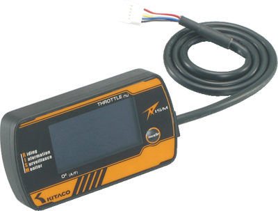

I-MAPでのオリジナル燃調マップの作成において、スロットル開度&O2モニター(以下RISM)は必要不可欠なアイテムです。ここではRISMの配線加工をメインに解説していきます。汎用パーツですので、車種ごとに加工箇所が異なります。当社が取り扱っているI-MAPの取付説明書も併せて、作業を進めて下さい。
Throttle opening & O2 monitor (RISM) are must for making original map with I-MAP. Here are wiring mods for RISM. Please refer to Kitaco I-MAP instruction together.
1 取付作業前に・・・ 1 Before installing...
必要な特殊工具 SPECIAL TOOLS
ドライバーやソケットレンチ等、一般工具を用意した上で、今回の取付にあたっての配線加工用工具は下記のものを使用します。
電工ペンチは必ず用意して下さい。電工ペンチはホームセンターでも売っていますので、そちらで手に入れる事が可能です。その他ニッパーやリード線の被膜剥がしに便利なワイヤーストリッパーがあると作業は捗りますが、電工ペンチだけでもニッパーの機能、被膜剥がしの機能を備える物がありますので、必要な分だけ用意しておいて下さい。
In addition to general tools such as drivers & sockets, special tools are required for wiring mods. CRIMPER is required which can be sold in home improvement store. NIPPER & WIRE STRIPPER are convenient if you have in hand, but CRIMPER might have same functions. Prepare for what you think required.
電工ペンチ CRIMPER
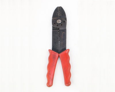
端子を圧着させます。 Crimps terminals
ワイヤーストリッパー WIRE STRIPPER
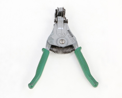
リード線被膜の剥ぎ取りに便利です。 Removes cable coating
ニッパー NIPPER
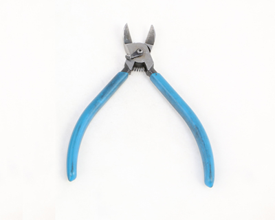
リード線をカットします。 Cuts lead wire
別途用意しておくパーツ OTHER PARTS REQUIRED
工具の他、装着に関してのパーツを下記を参考に必要に応じて別途ご用意下さい。これらのパーツは当社でも取り扱っています。画像をクリックすると商品ページにジャンプします。
Following parts as well as above tools are required (sold separately). Click the images to jump to the individual pages.

ギボシ端子SET CONNECTOR SET
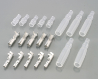
配線の加工に必要なオス、メスのギボシSETです。車両メーカーにより、サイズが異なりますので、ご注意下さい。
Male/Femail coupler set which you need for wiring mods. Size are different according to makers.
丸型端子SET RING TYPE TERMINAL SET
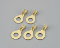
バッテリーのターミナルに接続する場合の丸型端子SETです。バッテリーのターミナルのボルトサイズに合わせてご購入下さい。
Round shape terminal set to connect with battery terminals. Purchase for your bolts.
面ファスナー HOOK AND LOOP FASTENER
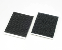
RISM本体の装着に便利なマジックテープです。車体にそのまま貼り付けての設置や、ユニバーサルプレートへの装着に大変便利です。
Hook & loop fastener very convenient when installing RISM body. Attach it to vehicle or universal plate.
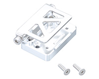
ユニバーサルプレート UNIVERSAL PLATE
RISM本体の取付に最適なサイズの汎用プレートです。運転中見やすい位置に他の部品と共締めして使用します。
Universal plate to attach RISM. Place it to somewhere easy to look while driving.
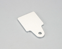
マスターシリンダーキャップ MUSTER CYLINDER CAP
RISM本体の取付に最適なマスターシリンダーキャップです。車種により取付可能です。
Master cylinder cap which is good to attach RISM. A lot of models usable.
作業にあたって注意する事 ATTENTION BEFORE OPERATION
作業にあたっていくつかの注意事項があります。下記を参考に、安全、確実に取付を行って下さい。 There are something that are must or must not to do. Make sure to install securely refering to following instruction for safety.
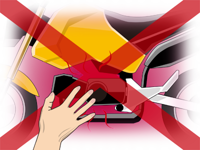
エンジン冷間時に作業を行う事
エンジン、マフラー直近のパーツに触れる場合もありますので、火傷には十分注意して下さい。
Make sure that the engine is cool enough before operation.

取り外したパーツ、ビス類はパーツごとに分類しておく
ビス類の小物を無くさないようにしっかりと保管して下さい。
Keep removed parts and screws classified. (Not to miss them)
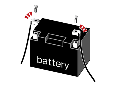
バッテリー端子は外して作業する
(-)端子から外していきます。
Remove battery terminals during operation
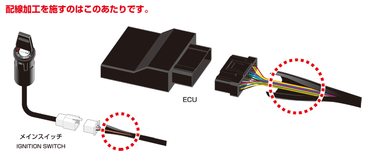
2 主な配線加工箇所 2 Place to making mods
主な配線加工箇所は車種により異なりますが、ECUにつながっている配線とメインスイッチにつながっている配線となります。I-MAPの取付説明書やメーカーサービスマニュアルを参考にし、外装部品を取り外していきます。 Place to making mods is mainly the wires between ECU & ignition switch. Start removing outside plastic, refering to maker's service manual & I-MAP instruction,
3 RISMの配線について 3 Wirings for RISM
RISMからの配線は計5本出ています。それぞれの配線を各車体配線に接続していきます。 There are 5 wires from RISM. Connect them one by one.

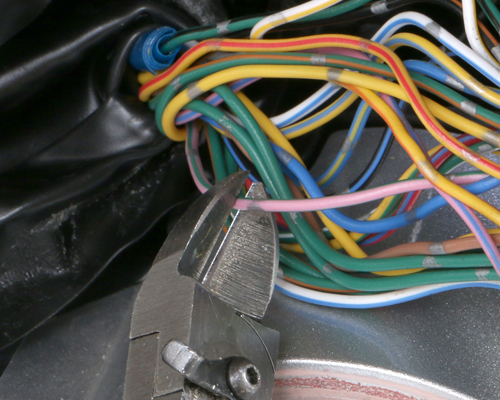
4 車種別配線加工箇所 4 Wiring details for specific models
配線加工箇所は車種により異なります。下図を参考にしてそれぞれ配線加工していきます。加工を施す箇所はカプラーからある程度の長さを取ったあたりをお奨めします。その辺りまで、配線を束ねている保護チューブをカットして下さい。 Wiring place differs from model & year. Refer to folloing illustration and make mods. Do not cut from the root, as some length requires to make mods. Let's cut the protection tube.
5 加工手順 5 Wiring
ここからが配線加工の本番ですが、その前に基本的なパーツの名称と加工手順を説明します。 The names of wiring parts are as follows
ギボシの名称 NAMES OF COUPLERS
リード線をカットして、別途購入した下記のギボシを圧着していきます。
(丸端子の圧着も同様の手順です。)
These comes with I-MAP. Cut the lead wires & crimp them.
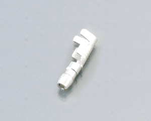
ギボシ端子(オス) COUPLER (MALE)
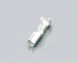
ギボシ端子(メス) COUPLER (FEMALE)
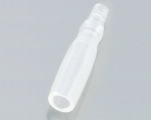
スリーブ(オス) SLEEVE (MALE)
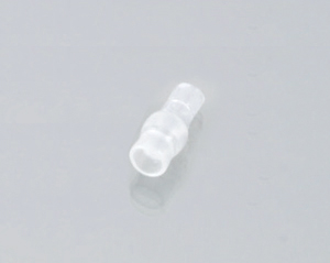
スリーブ(メス) SLEEVE (FEMALE)
加工作業の一覧 WIRING MODS
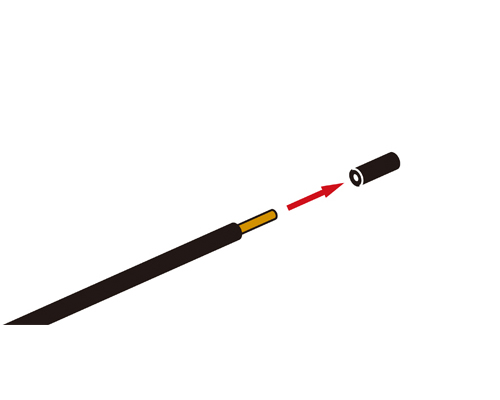
リード線のカットからギボシの圧着までの一連の作業です。 Operation from lead wire cut to coupler crimps
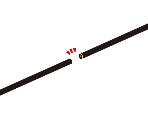
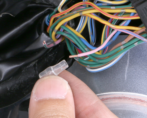
 ニッパー等でリード線を切断します。切断する位置はギボシを圧着するため、長さに余裕を持って切断します。
Cut lead wire with nipper. Leave some length as coupler crimp requires certain length.
ニッパー等でリード線を切断します。切断する位置はギボシを圧着するため、長さに余裕を持って切断します。
Cut lead wire with nipper. Leave some length as coupler crimp requires certain length.
1
 ワイヤーストリッパー等でリード線の被膜を5mm程剥がします。
Scrape 5mm coating from lead wire with wire stripper.
ワイヤーストリッパー等でリード線の被膜を5mm程剥がします。
Scrape 5mm coating from lead wire with wire stripper.
2
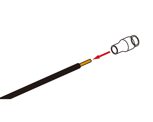
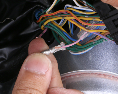
 スリーブを先にリード線に通しておきます。スリーブは絶縁処理に大変重要なパーツです。忘れずに必ず装着して下さい。忘れると、他のギボシと接触や雨水等でショートしてしまい、機器の破損にもつながります。
Firstly, sleeve should be left into lead wire, which is really important for insulation. Without installing, it will cause short circuit with rain or contact with other wires.
スリーブを先にリード線に通しておきます。スリーブは絶縁処理に大変重要なパーツです。忘れずに必ず装着して下さい。忘れると、他のギボシと接触や雨水等でショートしてしまい、機器の破損にもつながります。
Firstly, sleeve should be left into lead wire, which is really important for insulation. Without installing, it will cause short circuit with rain or contact with other wires.
3
 リード線にギボシをセットします。オス、メスが2種類ありますので、間違えないように注意して下さい。これから圧着していきますが、圧着箇所は2か所です。一つはリード線被膜、もう一つはリード線内の心線です。
Install lead wires to coupler. Do not connect incorrectly as there are male and female wires. Crimp 2 places for 1 lead wire. One is lead coating. The other is lead core cable.
リード線にギボシをセットします。オス、メスが2種類ありますので、間違えないように注意して下さい。これから圧着していきますが、圧着箇所は2か所です。一つはリード線被膜、もう一つはリード線内の心線です。
Install lead wires to coupler. Do not connect incorrectly as there are male and female wires. Crimp 2 places for 1 lead wire. One is lead coating. The other is lead core cable.
4

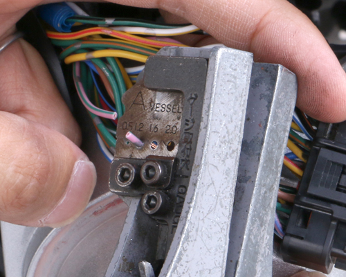
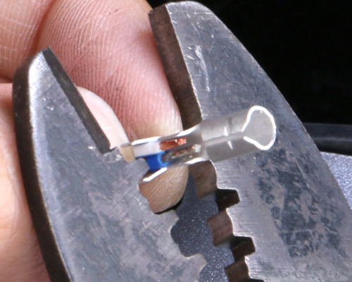
 電工ペンチでリード線にギボシを圧着します。電工ペンチの歯に沿うようにギボシの爪を曲げていき、リード線被膜、心線に爪をくいこませます。
Crimp lead wire to coupler with crimper. Align with its teeth, bend couplers inside the lead coating and core cable.
電工ペンチでリード線にギボシを圧着します。電工ペンチの歯に沿うようにギボシの爪を曲げていき、リード線被膜、心線に爪をくいこませます。
Crimp lead wire to coupler with crimper. Align with its teeth, bend couplers inside the lead coating and core cable.
5
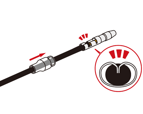
 爪がリード線被膜、心線にくいこまれているか確認し、スリーブをギボシに被せます。
Make sure that the pawls of coupler are inside the wire. Cover the coupler with sleeve.
爪がリード線被膜、心線にくいこまれているか確認し、スリーブをギボシに被せます。
Make sure that the pawls of coupler are inside the wire. Cover the coupler with sleeve.
6
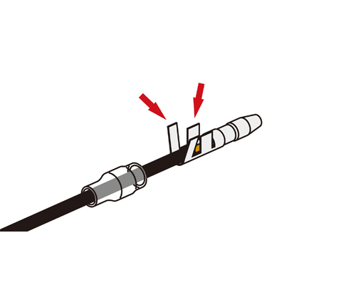
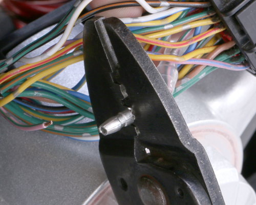
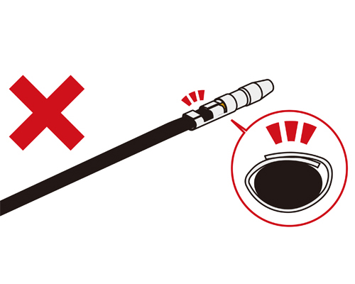 電工ペンチを使わずに一般のペンチやプライヤーで圧着してしまう悪い例です。この例ですと、爪がリード線被膜、心線にくいこまれておらず、ギボシが抜けてしまいます。圧着作業は必ず電工ペンチを使用し、確実に爪がくいこむ様に行って下さい。
Do not use general pench or plier. It causes the pawls do not come inside the core wire, and coupler falls down and be disconnected. Use crimper and make sure of above operation.
電工ペンチを使わずに一般のペンチやプライヤーで圧着してしまう悪い例です。この例ですと、爪がリード線被膜、心線にくいこまれておらず、ギボシが抜けてしまいます。圧着作業は必ず電工ペンチを使用し、確実に爪がくいこむ様に行って下さい。
Do not use general pench or plier. It causes the pawls do not come inside the core wire, and coupler falls down and be disconnected. Use crimper and make sure of above operation.
▲
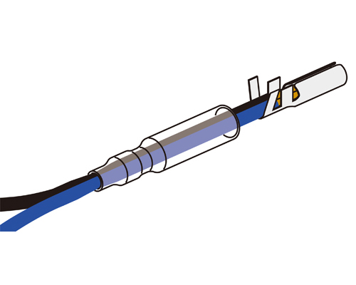
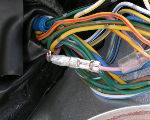
 中には1つのギボシにリード線を2つ圧着する場合があります。少々キツいですが、1本の場合と同様の手順で、2本まとめて電工ペンチで圧着します。もちろんスリーブも忘れずに2本共に通しておきます。
Sometimes, 2 lead wires are crimped in 1 coupler. Do not forget to use sleeves for sure.
中には1つのギボシにリード線を2つ圧着する場合があります。少々キツいですが、1本の場合と同様の手順で、2本まとめて電工ペンチで圧着します。もちろんスリーブも忘れずに2本共に通しておきます。
Sometimes, 2 lead wires are crimped in 1 coupler. Do not forget to use sleeves for sure.
7
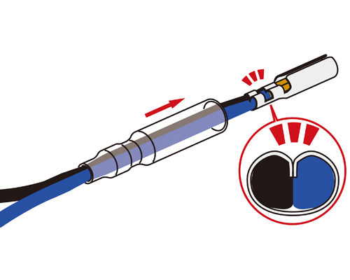
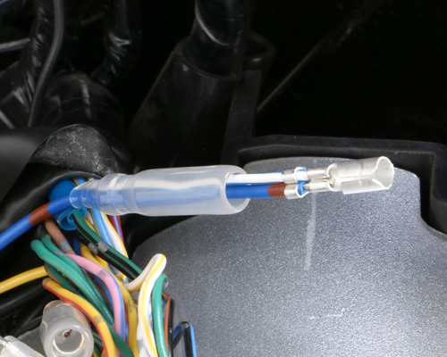 爪がリード線被膜、心線にくいこまれているか確認し、スリーブをギボシに被せます。
Pawls are inside the lead coating and core wire, cover the coupler with sleeve.
爪がリード線被膜、心線にくいこまれているか確認し、スリーブをギボシに被せます。
Pawls are inside the lead coating and core wire, cover the coupler with sleeve.
8
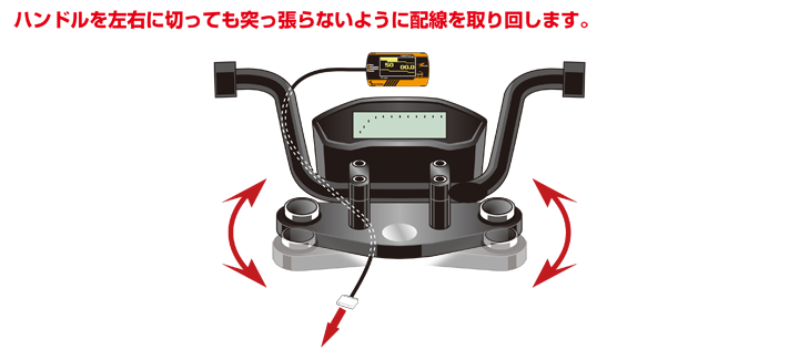
6 配線の取り回し 6 Routing the wire
配線加工後、RISMの配線を束ねて、車体配線に沿うようにハンドル周りまで取り回します。ハンドルを左右に切った際、配線が突っ張らないようにして下さい。 Bundle wires and route to the handle bar. The wiring should be some swag not to stretch too tight to interfere with handling.
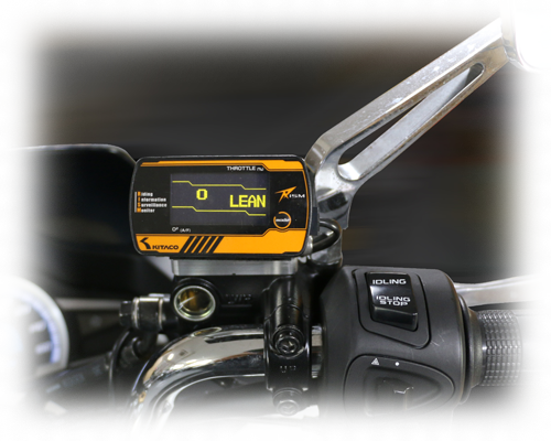
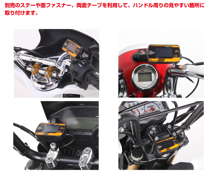
7 RISM本体の取付 7 Installing RISM BODY
ステー類を使用し、走行中見やすい位置にRISM本体を設置します。運転に支障が無いように取り付けて下さい。 Using universal plate, install RISM to somewhere easy to see while driving
8 動作確認 8 Operation Check
バッテリー端子を接続し、メインスイッチをONにします。(エンジンは始動しません)
RISMに電源が入れば、接続は完了です。取付説明書を参考にスロットルの全閉、全開の設定を行って下さい。
Connect battery terminals and turn on the main switch. (Engine does not start). If RISM starts, connecting is completed. Please set up throttle closing and opening setting refering to instruction manual.

9 配線処理 9 Wiring Treatment
あとはカットした保護チューブにハーネステープを巻きつけて、取り外した外装部品を元通り取り付けます。 Bundle the cables in cut tube with harness tape and reinstall outside plastics.