


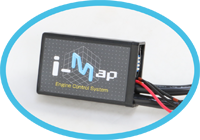
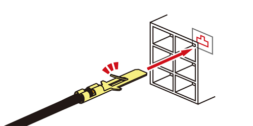
取付難易度が高そうなI-MAP、しかしFI車が当たり前の昨今、もはやI-MAPはチューニングには欠かせないアイテムです。ここではチューニングベース車として人気の高いグロムへのI-MAPの取付手順を画像を踏まえて解説していきます。初めてチューニングをされる方は「壊れたらどうしよう・・・」とチューニングに二の足を踏まれている方もいらっしゃるかと思われますが、きちんと説明通りに一つ一つ確実に作業を行えば大丈夫です。
It seems the hardle to install I-MAP is very high, but it becomes "must" for engine tuning. We are going to explain how to install KITACO I-MAP on GROM step by step, which is so great if installed correctly!
取付作業前に・・・/ Before installing...
必要な特殊工具 / SPECIAL TOOLS
ドライバーやソケットレンチ等、一般工具を用意した上で、今回の取付にあたっての配線加工用工具は下記のものを使用します。
電工ペンチは必ず用意して下さい。電工ペンチはホームセンターでも売っていますので、そちらで手に入れる事が可能です。その他ニッパーやリード線の被膜剥がしに便利なワイヤーストリッパーがあると作業は捗りますが、電工ペンチだけでもニッパーの機能、被膜剥がしの機能を備える物がありますので、必要な分だけ用意しておいて下さい。
In addition to general tools such as drivers & sockets, special tools are required for wiring mods. CRIMPER are required which can be sold in home improvement store. NIPPER & WIRE STRIPPER are convenient if you have in hand, but CRIMPER might have same functions. Prepare for what you think required.
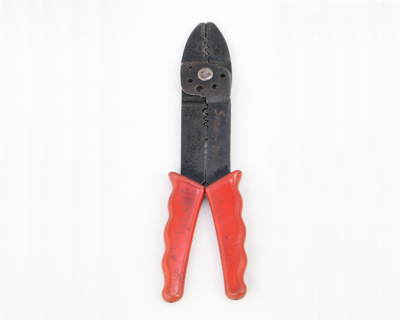
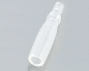
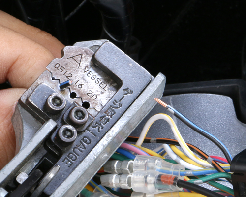
■電工ペンチ
端子を圧着させます。
CRIMPER
Crimps terminals
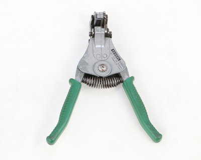
■ワイヤーストリッパー
リード線被膜の剥ぎ取りに便利です。
WIRE STRIPPER
Removes cable coating
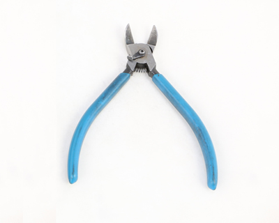
■ニッパー
リード線をカットします。
NIPPER
Cuts lead wire
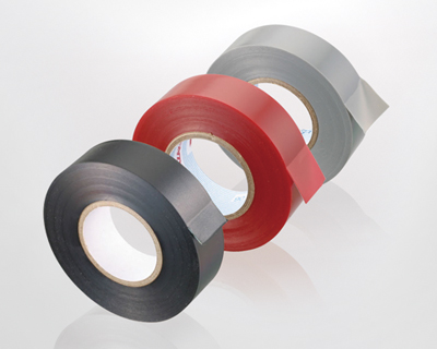
別途用意しておくと便利なもの / SOMETHING CONVENIENT IF ANY
工具の他、装着に関して、あると便利なのは下記のものです。
ハーネスをまとめるハーネステープや、I-MAP本体の防振に役に立つスポンジシート等の使用をオススメします。これらは当社でも取り扱っています。
In addition to tools, there are something covenient if you have in hand.
Harness tapes to collect harnesses, sponge sheet for anti-vibration are recommended, which are also sold in Kitaco.
作業にあたって注意する事 / ATTENTION BEFORE OPERATION
●エンジン冷間時に作業を行う事(マフラー直近のビス類を外しますので、火傷等には注意して下さい)
●取り外したパーツ、ビス類はパーツごとに分類しておく(ビス類の小物を無くさないようにしっかりと保管して下さい)
●Make sure that the engine is cool enough before operation. (Be careful not to get burned when removing screws close to mufflers)
●Keep removed parts and screws classified. (Not to miss them)
CAPTION:1A シートの取り外し / REMOVING SEAT
それでは作業開始!まずはシートの取り外しです。車体左側のキー差し込み、回してシートを斜め後ろに引き上げます。
First, remove seat. Insert key to left side body. Pull the seat to upward and backward.
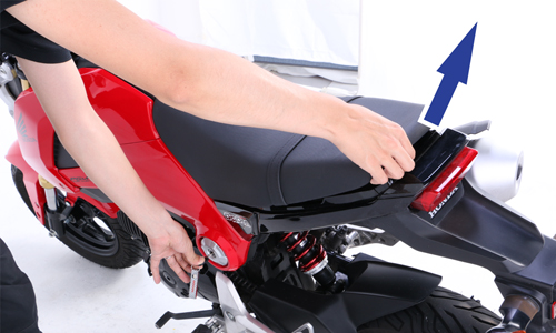 新車状態だとシートの脱着が渋いかもしれません。
Might be hard to remove if seat is new.
CAPTION:1B サイドシュラウドのビス、トリムクリップの取り外し
REMOVING SIDE SHROUD SCREWS AND TRIM CLIPS.
次に左右のサイドシュラウドを取り外します。取り外しには+スクリューとトリムクリップ、ボタンキャップボルトを外します。
Remove ( + ) screws, trim clips & button cap bolts. Remove left and right side shround.
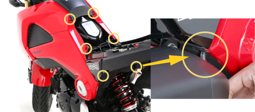 まずは画像の6か所のスクリュー、トリムクリップを外します。車体右側下部のトリムクリップはマフラーの直近にありますので、マフラーの熱い内の作業は行わないで下さい。
Remove 6 of screws and trim clips. Do not opearte while engine is hot as trim clips are placed near muffler.
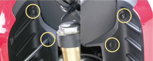 前側は左右2か所ずつ、計4か所のスクリュー、トリムクリップを外します。
Remove each of left and right for front and rear screws and trim clips.
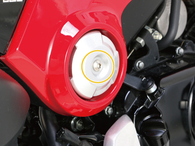
 車体右側はサイドキャップを外して、その下にあるボルトを取り外します。
Remove right side cap, and remove bolts under it.
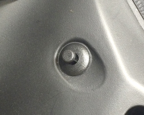
トリムクリップはどうやって脱着する? / HOW DO I REMOVE TRIM CLIPS?
1
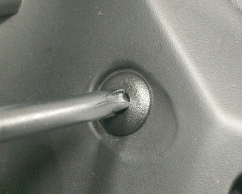
2
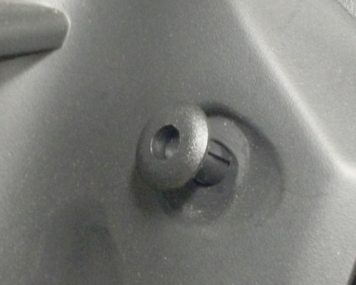
外す際は真ん中のピンをドライバー等で軽く押し込むとロックが解除され、外せます。
Push center pin with driver to unlock to remove.
1
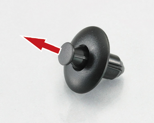
2
3
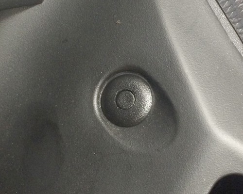
付ける際は一旦ピンを押し出して、カウルの取付穴にセットし、真ん中のピンを軽く押し込むとロックが掛かります。
Pull out and keep the pins extruding, insert them to the cowling. Push center of the pins softly to lock.
CAPTION:1C サイドシュラウドの取り外し / REMOVING SIDE SHROUD
+スクリューとトリムクリップを全て外すと、車体側グロメットから爪(クリップ)を外しながらサイドシュラウドを車体から引き抜きます。引き抜きは順序があります。順序を間違えたり、強引に引き抜いてしまうと、爪が折れたりしますので慎重に作業を行って下さい。
After removing all the ( + ) screws and trim clips with pawls removed, pull out side shroud from vehicle. How to pull is in consecutive order.
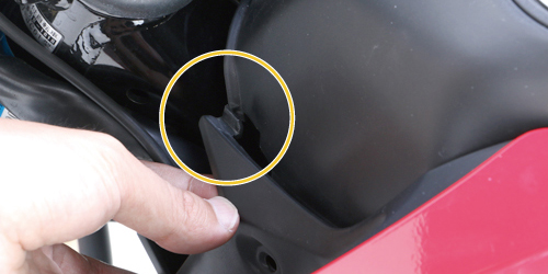 前側のサイドシュラウドの爪を外します。
Remove pawls front side shroud.
 サイドシュラウドの上側を横に引き抜き、裏面上側の爪を外します。
Pull the upper side shroud horizontally, remove pawls.
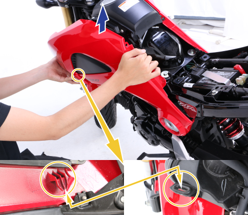 次はサイドシュラウドを上に持ち上げて、裏面下側の爪を外すとサイドシュラウドが取り外せます。横に引き抜きすぎると、下側の爪が折れますのでご注意下さい。
Next, lift up side shroud, remove bottom side of backside, to remove side shroud. Pulling it horizontally too much causes the bottom pawl's breakage.
CAPTION:1D シートカウルのボルト、ビス、トリムクリップの取り外し / REMOVING SEAT COWL BOLTS, SCREWS & TRIM CLIPS.
サイドシュラウドを外すと、次はシートカウルの取り外しです。シートカウルも各部のボルト、スクリュー、トリムクリップを外していきます。
After side shroud, next it is seat cowl removal. Remove seat cowl bolts, screws & trim clips.
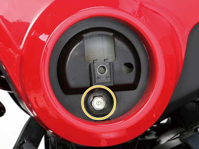
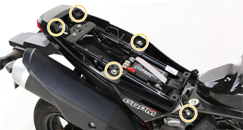 シートカウル上面からボルト、スクリュー計4か所と右側からボルト1か所を外します。
Remove bolts & screws from 4 places of seat cowl upper side. Remove bolt from right side.
 シートカウル左側からボルト、スクリューを計2か所を外します。
Remove bolts & screws from 2 places of seat left side of cowl.
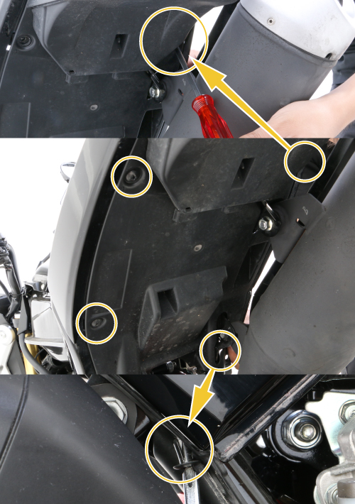 シートカウル裏面からスクリュー、トリムクリップを計4か所外します。
Remove screws & trim clips from 4 places of seat cowl backside.
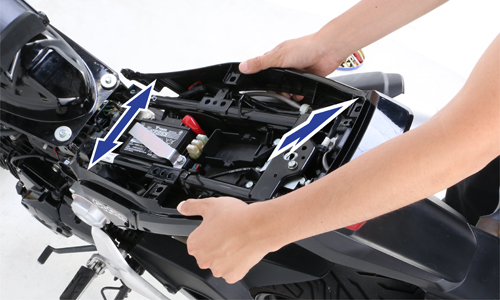
CAPTION:1E シートカウルの取り外し / REMOVING SEAT COWL
ボルト、スクリュー、トリムクリップを全て外し、シートカウルを左右に広げて、後ろに引き抜くと外れます。
After removing all the bolts, screws & trim clips, spread seat cowl and pull it backward.
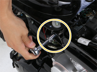
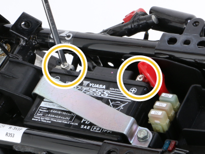
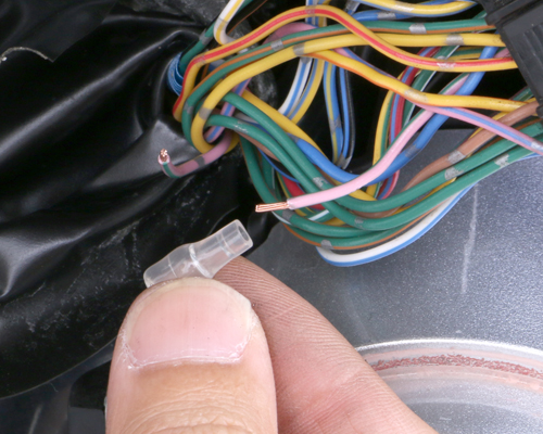
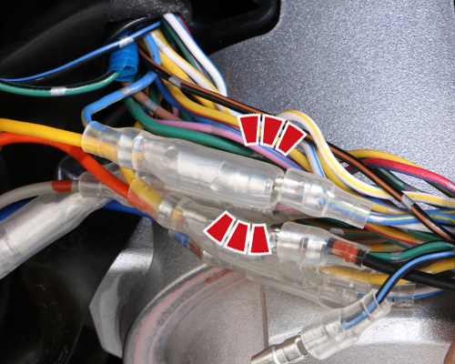
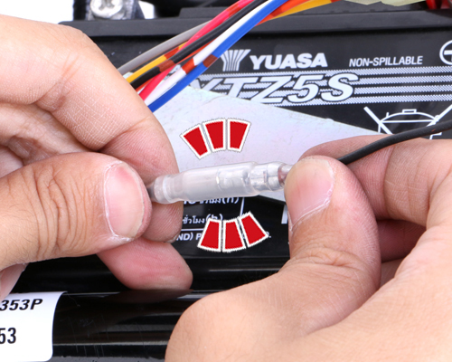
CAPTION:2A バッテリー端子の取り外し / REMOVING BATTERY TERMINALS
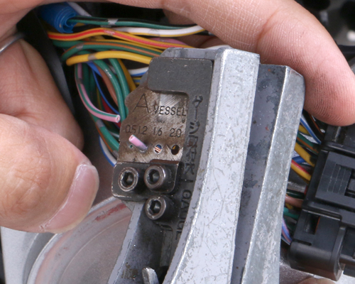
シートカウルを取り外すと車体左側にECUが見えてきました。これからECUの配線を加工していきますが、その前にバッテリー端子を外しておきましょう。バッテリー端子は(-)側から外します。
After removing seat cowl, you can see ECU on left side. Disconnect battery terminals before starting wiring mods. Remove ( - ) side first.
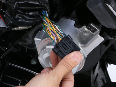
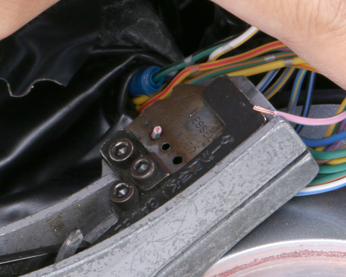
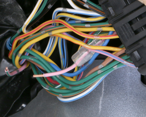
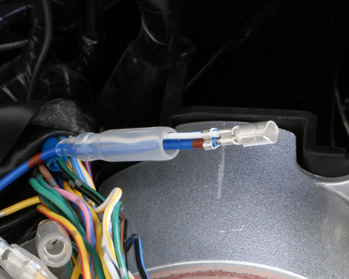
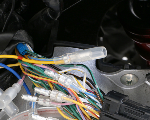
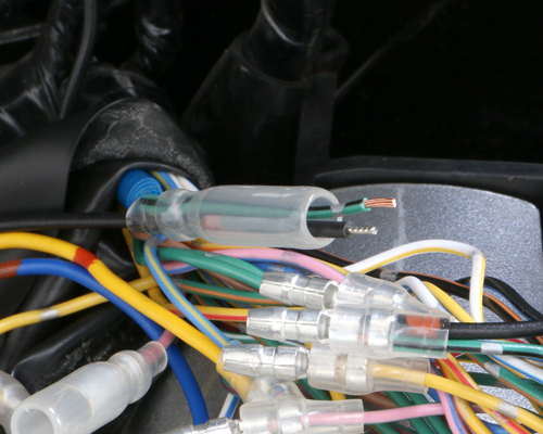
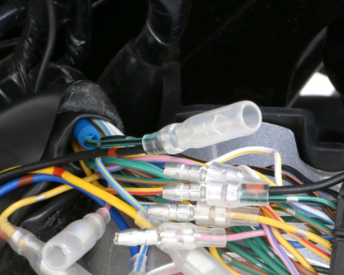
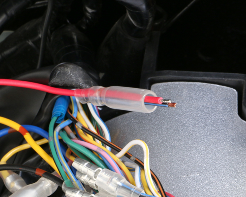
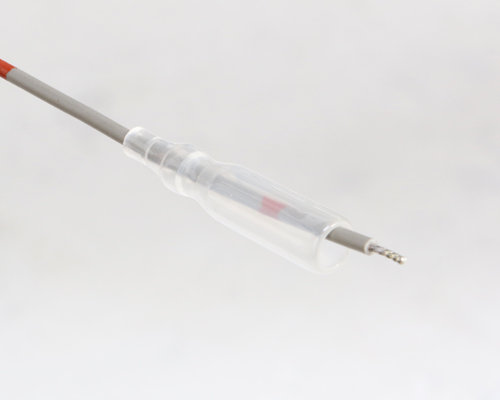
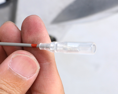
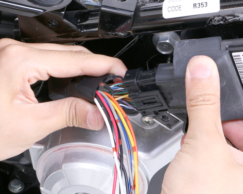
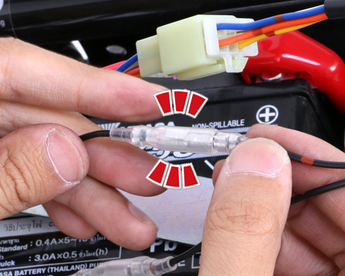
CAPTION:2B 33Pカプラーの取り外しと保護チューブの剥ぎ取り / REMOVING 33P COUPLER & PROTECTION TUBE
車体左側のECUから33Pカプラーを外して、33Pカプラー側の保護チューブを剥がします。
Remove ECU out of 33P coupler, remove protection tube.
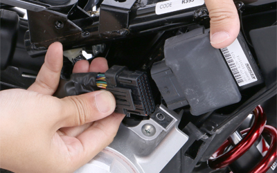 33Pカプラーは爪を起こすと取り外せます。
Lift-up pawls and remove 33P coupler.
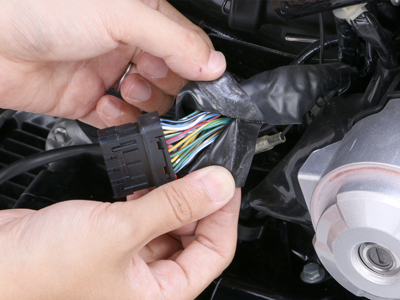
 リード線の加工がしやすい様に、ある程度保護チューブを剥がします。
Remove some protection tube for wiring.
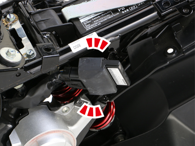
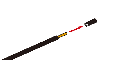
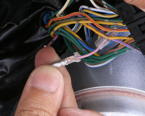
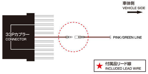
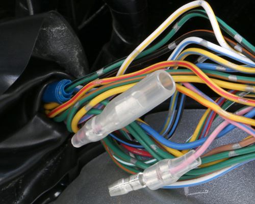
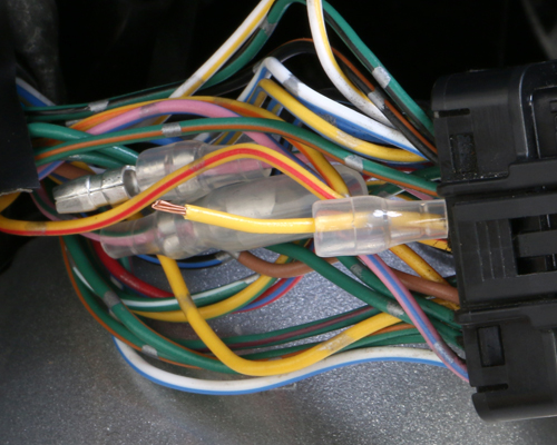
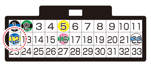
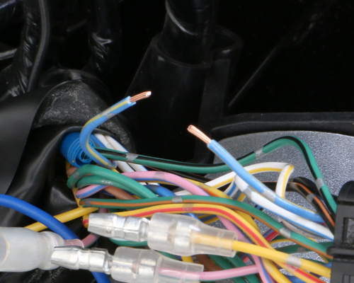
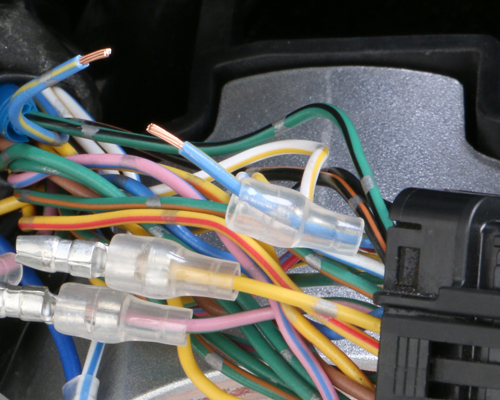
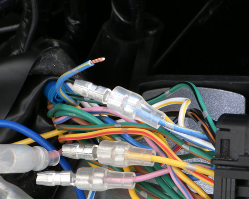
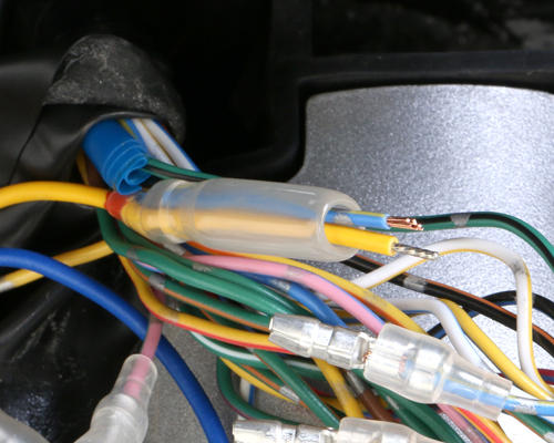
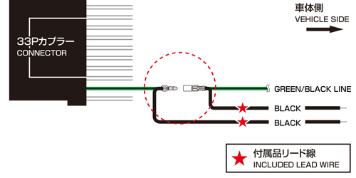
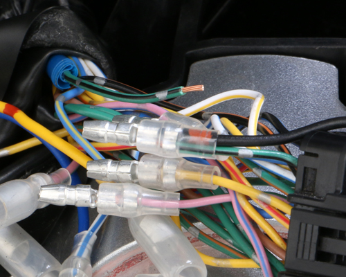
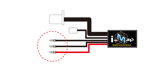
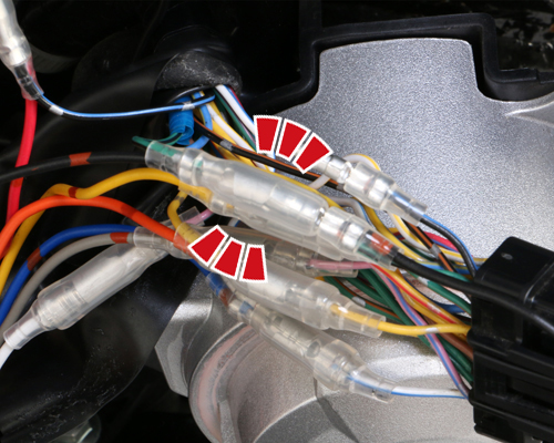
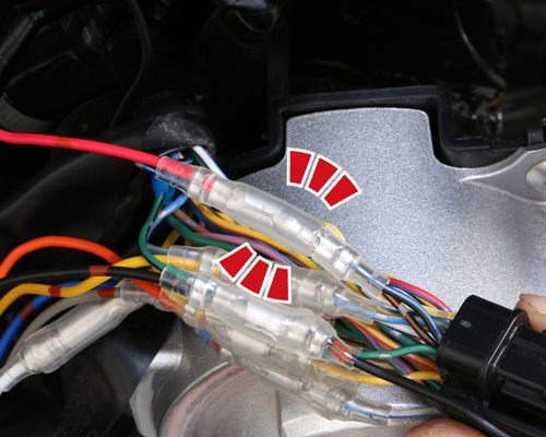
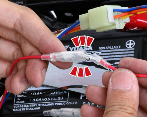
CAPTION:2C 加工場所の確認 / THE MODIFICATION PART
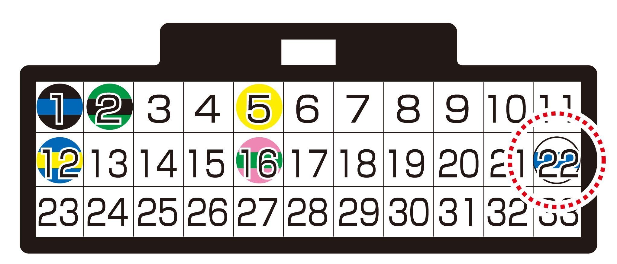
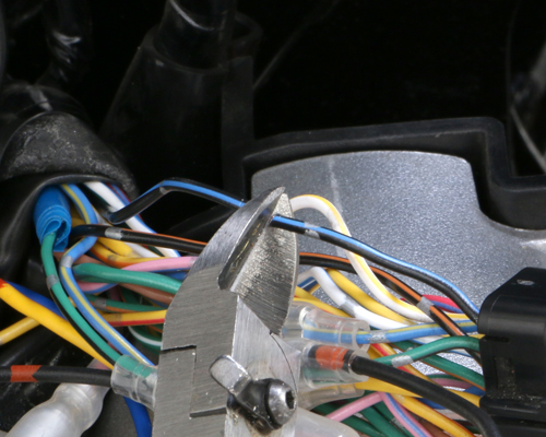
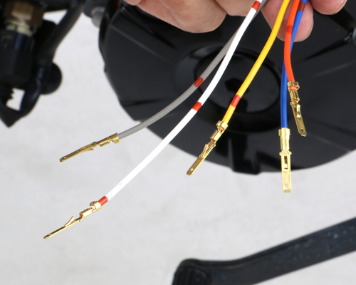
33Pカプラーには数多くのリード線がつながっています。加工を施すリード線の色、箇所を間違えないように確認しつつ慎重に行いましょう。また車種により、別の箇所に同じ色のリード線が存在している場合もあるため、やみくもに「同じ色だから・・」と間違ったリード線に加工を施さないように注意して下さい。
A lot of colorful lead wires come from 33P coupler. Make wiring modification without making wrong wiring. There are same color wires in other place, so please be patient and be careful.
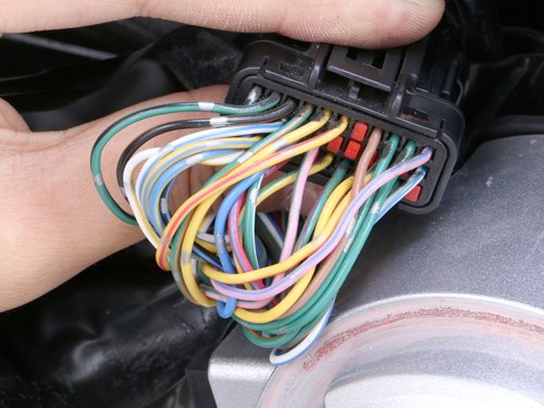
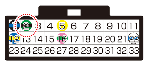
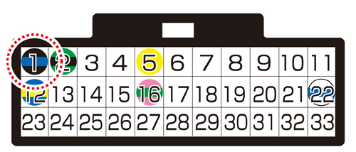
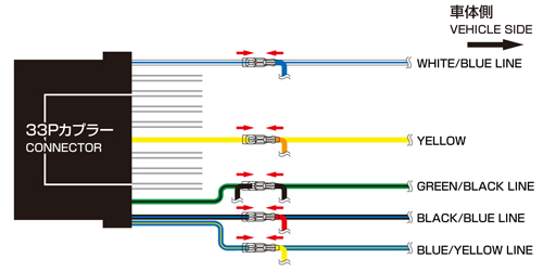
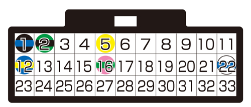 上の画像のカプラーの方向から見て、下図の位置のリード線を加工していきます。
Looking from the wiring side of coupler, make modification of lead wires.
CAPTION:3A 加工手順の説明 / HOW TO MAKE MODIFICATION
ここからが配線加工の本番ですが、その前に基本的なパーツの名称と加工手順を説明します。
The names of wiring parts are as follows
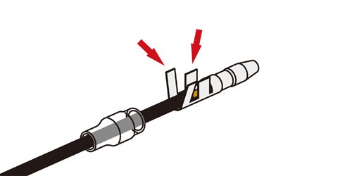
加工に必要なパーツ / REQUIRED PARTS
これらはI-MAPに付属されています。リード線をカットして、これらを圧着していきます。
These comes with I-MAP. Cut the lead wires & crimp them.
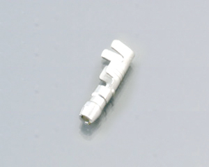
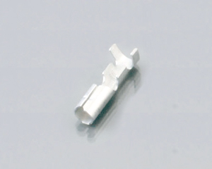
■ギボシ端子(オス)
COUPLER (MALE)
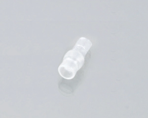
■ギボシ端子(メス)
COUPLER (FEMALE)
■スリーブ(オス)
SLEEVE (MALE)
■スリーブ(メス)
SLEEVE (FEMALE)
加工作業の一覧 / WIRING MODS
リード線のカットからギボシの圧着までの一連の作業です。
Operation from lead wire cut to coupler crimps

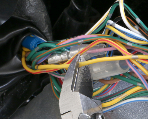
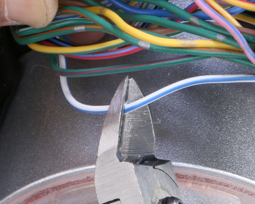
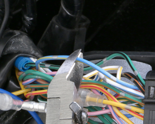
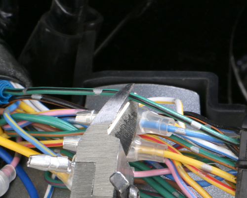
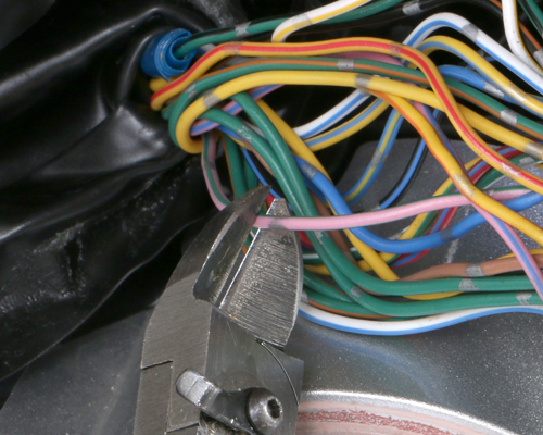 ニッパー等でリード線を切断します。切断する位置はギボシを圧着するため、長さに余裕を持って切断します。
Cut lead wire with nipper. Leave some length as coupler crimp requires certain length.
1
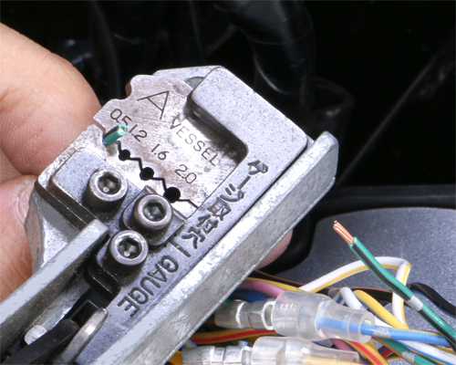
 ワイヤーストリッパー等でリード線の被膜を5mm程剥がします。
Scrape 5mm coating from lead wire with wire stripper.
2
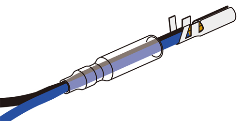
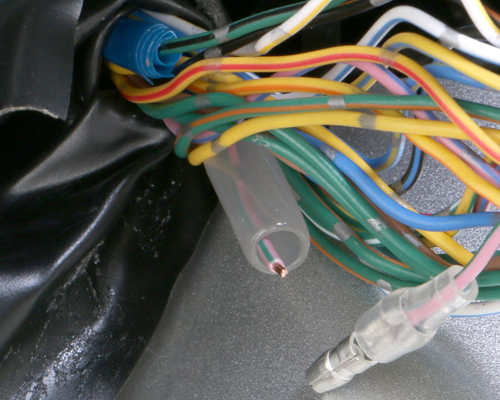
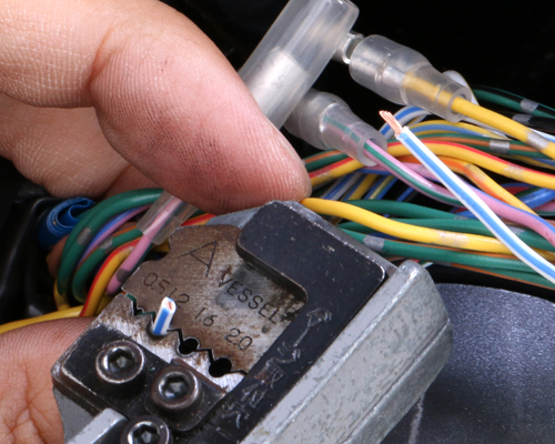
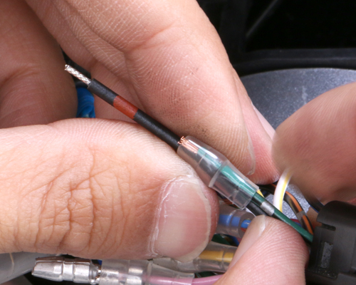
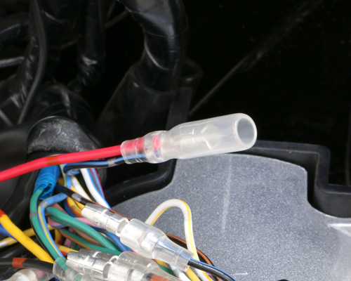
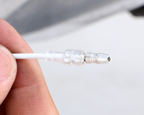
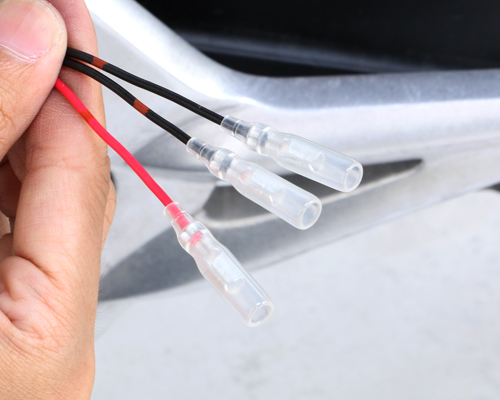
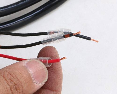
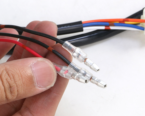
 スリーブを先にリード線に通しておきます。スリーブは絶縁処理に大変重要なパーツです。忘れずに必ず装着して下さい。忘れると、他のギボシと接触や雨水等でショートしてしまい、機器の破損にもつながります。
Firstly, sleeve should be let into lead wire, which is really important for insulation. Without installing, it will cause short circuit with rain or contact with other wires.
3
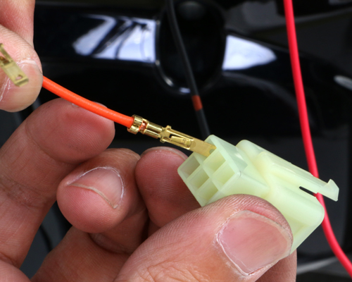
 リード線にギボシをセットします。オス、メスが2種類ありますので、間違えないように注意して下さい。これから圧着していきますが、圧着箇所は2か所です。一つはリード線被膜、もう一つはリード線内の心線です。
Install lead wires to coupler. Do not connect incorrectly as there are male and female wires. Crimp 2 places for 1 lead wire. One is lead coating. The other is lead core cable.
4
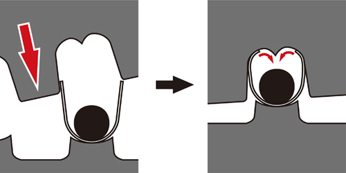
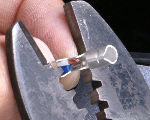
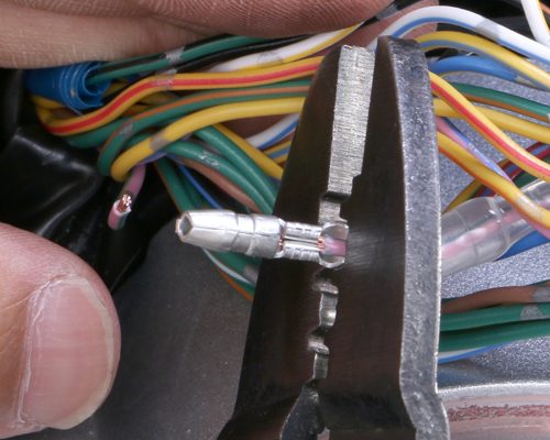
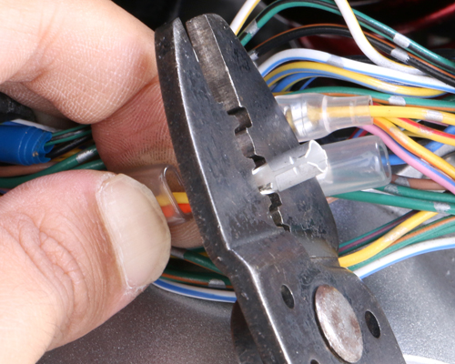
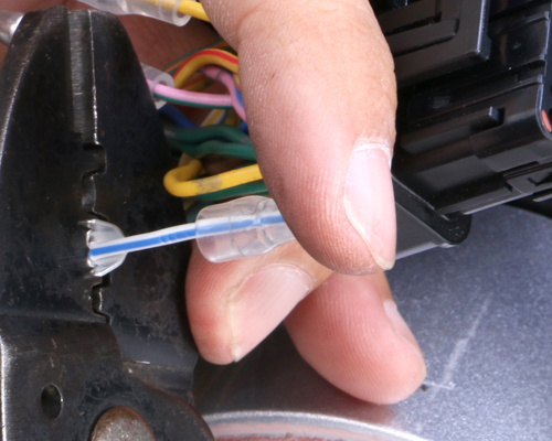
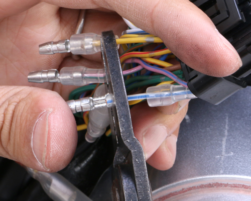
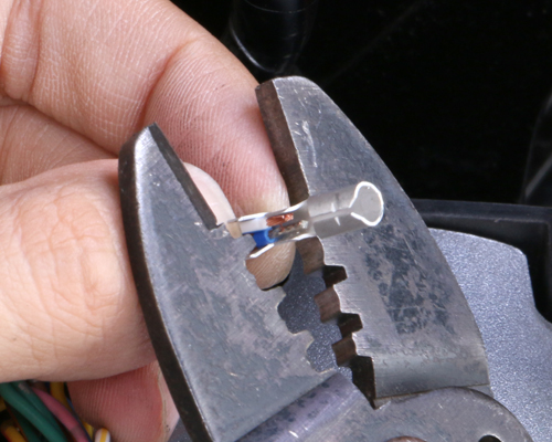
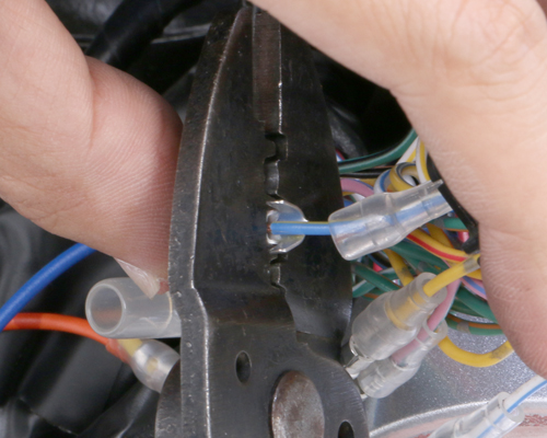
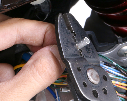
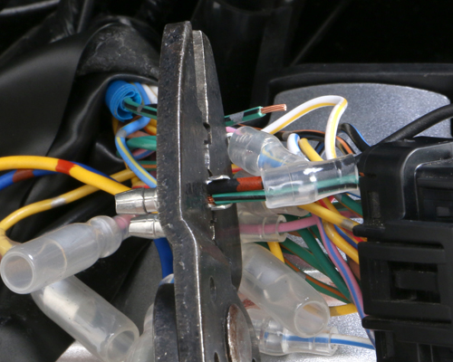
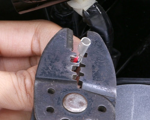
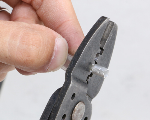
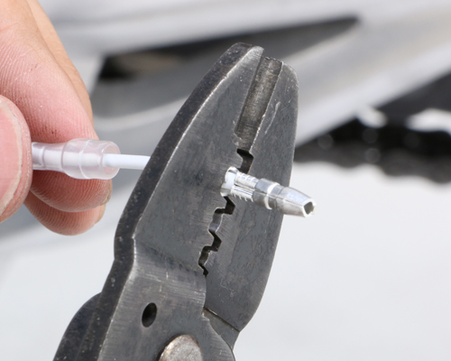
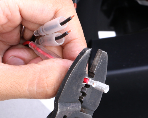
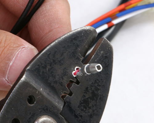
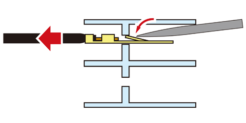
 電工ペンチでリード線にギボシを圧着します。電工ペンチの歯に沿うようにギボシの爪を曲げていき、リード線被膜、心線に爪をくいこませます。
Crimp lead wire to coupler with crimper. Align with its teeth, bend couplers inside the lead coating and core cable.
5
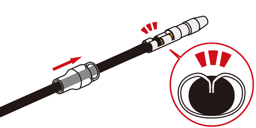
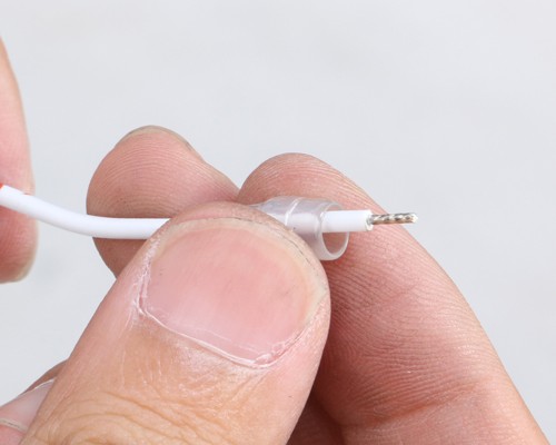
 爪がリード線被膜、心線にくいこまれているか確認し、スリーブをギボシに被せます。
Make sure that the pawls of coupler are inside the wire. Cover the coupler with sleeve.
6
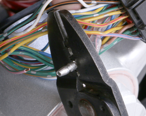
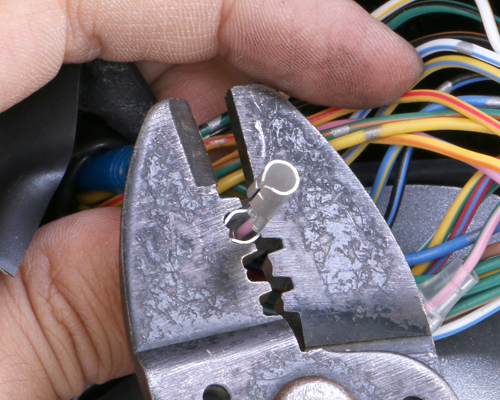
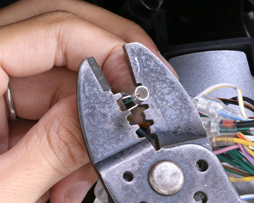
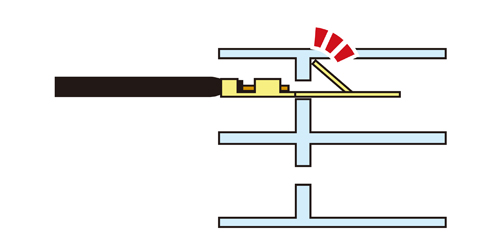
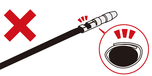 電工ペンチを使わずに一般のペンチやプライヤーで圧着してしまう悪い例です。この例ですと、爪がリード線被膜、心線にくいこまれておらず、ギボシが抜けてしまいます。圧着作業は必ず電工ペンチを使用し、確実に爪がくいこむ様に行って下さい。
Do not use general pench or plier. It causes the pawls do not come inside the core wire, and coupler falls down and be disconnected. Use crimper and make sure of above operation.
▲
 中には1つのギボシにリード線を2つ圧着する場合があります。少々キツいですが、1本の場合と同様の手順で、2本まとめて電工ペンチで圧着します。もちろんスリーブも忘れずに2本共に通しておきます。
Sometimes, 2 lead wires are crimped in 1 coupler. Do not forget to use sleeves for sure.
7
 爪がリード線被膜、心線にくいこまれているか確認し、スリーブをギボシに被せます。
Pawls are inside the lead coating and core wire, cover the coupler with sleeve.
8
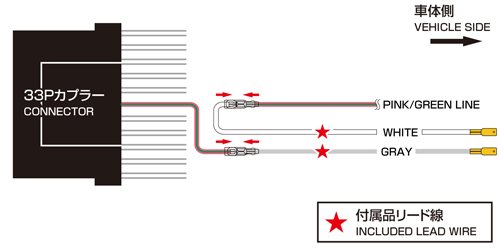
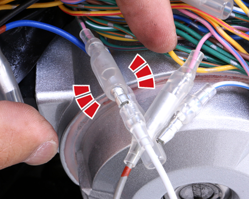
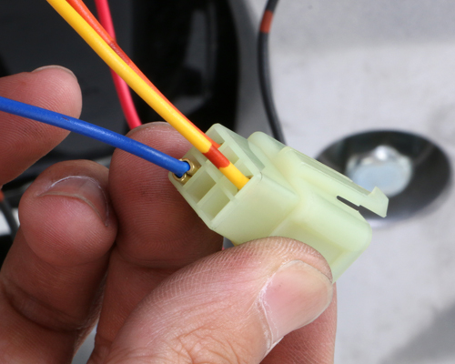
CAPTION:3B 16番・「桃色/緑ライン」のリード線加工 / NO. 16 PINK - GREEN LEAD WIRE MODS
まずは16番「桃色/緑色ライン」のリード線を切断し、上記の加工手順で記載した通り、リード線にスリーブ、ギボシを取り付けます。ギボシはカプラー側(ECU側)にオス、車体ハーネス側にメスとなります。
Cut NO. 16 "PINK/GREEN" wire, install sleeve and coupler as above written. Sleeve is on lead wire side. Male coupler is on ECU side. Female is for vehicle side.
 図のリード線を加工します。
Lead wire of illustration left
一連の加工動作です。/ MODIFICATION
1
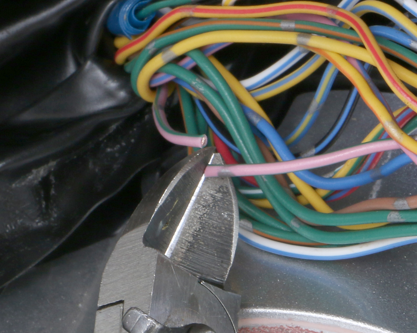
カットする
Cut the wire
2
被膜を剥がす
Remove coating
3
スリーブ(オス)を入れる
Insert sleeve (male)
4
ギボシ(オス)を圧着する
Crimp coupler (male)
5
ギボシ(オス)完成
Coupler (male) finished
6
スリーブ(メス)を入れる
Insert sleeve (female)
7
ギボシ(メス)を圧着する
Crimp coupler (female)
8
ギボシ(メス)完成
Coupler (female) finished
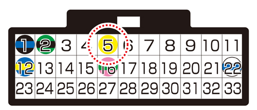
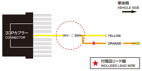
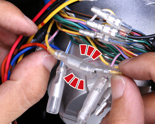
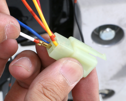
CAPTION:3C 5番・「黄色」のリード線加工 / NO.5 YELLOW LEAD WIRE MODS
続いて5番「黄色」のリード線を切断し、上記の加工手順で記載した通り、リード線にスリーブ、ギボシを取り付けます。ギボシはカプラー側(ECU側)にオス、車体ハーネス側にメスとなりますが、車体ハーネス側のメスギボシはI-MAPに付属されている「橙色(オレンジ色)」のリード線もまとめて、ギボシを圧着します。
※30番にも「黄色」のリード線が存在します。間違えないように注意して下さい。
Cut No.5 "YELLOW" lead wire, install sleeve and coupler as written above. Male coupler is ECU side, female is for vehicle side together with orange lead wire that includes in I-MAP.
※There is other ""YELLOW"" lead wire on No.30. Do not connect the wrong wire.
 図のリード線を加工します。
Make modification of left lead wire.
一連の加工動作です。/ WIRE MODIFICATION
1
カットする
Cut the wire
2
被膜を剥がす
Remove coating
3
スリーブ(オス)を入れる
Insert sleeve (male)
4
ギボシ(オス)を圧着する
Crimp coupler (male)
5
ギボシ(オス)完成
Coupler (male) finished
6
スリーブ(メス)を入れる
Insert sleeve (female)
7
ギボシ(メス)を圧着する
Crimp coupler (female)
8
ギボシ(メス)完成
Coupler (female) finished
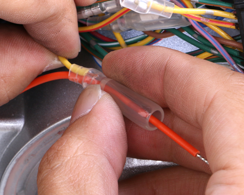
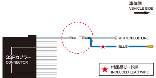
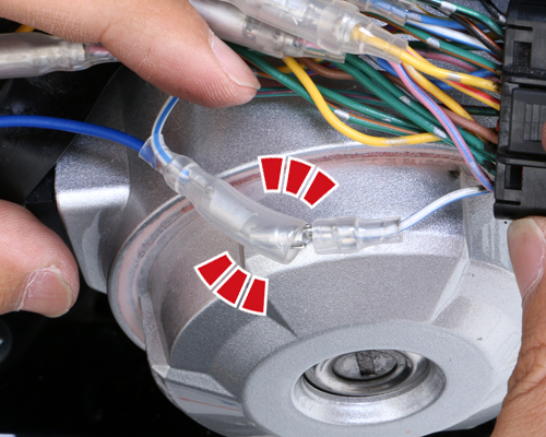
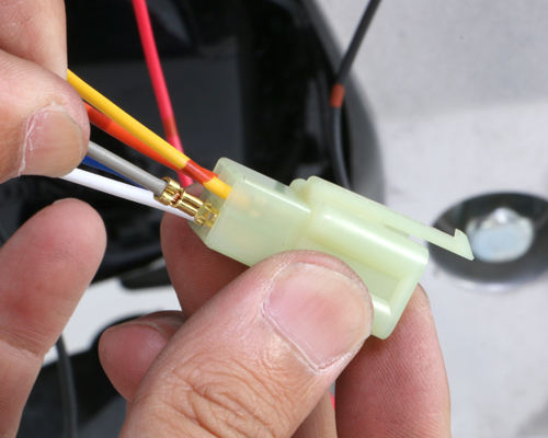
CAPTION:3D 22番・「白色/青色ライン」のリード線加工 / NO.22 WHITE - BLUE LEAD WIRE MODS
続いて22番「白色/青色ライン」のリード線を切断し、上記の加工手順で記載した通り、リード線にスリーブ、ギボシを取り付けます。ギボシはカプラー側(ECU側)にオス、車体ハーネス側にメスとなりますが、車体ハーネス側のメスギボシはI-MAPに付属されている「青色」のリード線もまとめて、ギボシを圧着します。
Cut No.22 "WHITE/BLUE" lead wire, install sleeve and couplers as written above. Male coupler is ECU side, female is for vehicle side together with "BLUE" lead wire that includes in I-MAP.
 図のリード線を加工します。
Make modification of left lead wire
一連の加工動作です。/ MODIFICATION
1
カットする
Cut the wire
2
被膜を剥がす
Remove coating
3
スリーブ(オス)を入れる
Insert sleeve (male)
4
ギボシ(オス)を圧着する
Crimp coupler (male)
5
ギボシ(オス)完成
Coupler (male) finished
6
スリーブ(メス)を入れる
Insert sleeve (female)
7
ギボシ(メス)を圧着する
Crimps coupler (female)
8
ギボシ(メス)完成
Coupler (female) finished
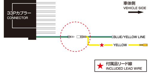
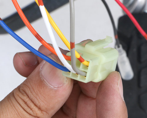
CAPTION:3E 12番・「青色/黄色ライン」のリード線加工 / NO.12 BLUE - YELLOW LEAD WIRE MODS
続いて12番「青色/黄色ライン」のリード線を切断し、上記の加工手順で記載した通り、リード線にスリーブ、ギボシを取り付けます。ギボシはカプラー側(ECU側)にオス、車体ハーネス側にメスとなりますが、車体ハーネス側のメスギボシはI-MAPに付属されている「黄色」のリード線もまとめて、ギボシを圧着します。
Cut No.12 "BLUE/YELLOW" lead wire, install sleeve and couplers as writen above. Male coupler is ECU side, female is for vehicle side together with "YELLOW" lead wire that includes in I-MAP
 図のリード線を加工します。
Make modification of left lead wire
一連の加工動作です。/ WIRE MODIFICATION
1
カットする
Cut the wire
2
被膜を剥がす
Remove coating
3
スリーブ(オス)を入れる
Insert sleeve (male)
4
ギボシ(オス)を圧着する
Crimp coupler (male)
5
ギボシ(オス)完成
Coupler (male) finished
6
スリーブ(メス)を入れる
Insert sleeve (female)
7
ギボシ(メス)を圧着する
Crimp coupler (female)
8
ギボシ(メス)完成
Coupler (female) finished
CAPTION:3F 2番・「緑色/黒色ライン」のリード線加工 / NO.2 GREEN - BLACK LEAD WIRE MODS
続いて2番「緑色/黒色ライン」のリード線を切断し、上記の加工手順で記載した通り、リード線にスリーブ、ギボシを取り付けます。ギボシはカプラー側(ECU側)にオス、車体ハーネス側にメスとなりますが、カプラー側のオスギボシと車体ハーネス側のメスギボシにはI-MAPに付属されている「黒色」のリード線もまとめて、ギボシを圧着します。
Cut No.2 "GREEN/BLACK" lead wire, install sleeve and couplers as written above. Male coupler is ECU side, female if for vehicle side together with "BLACK" lead wire that includes in I-MAP.
 図のリード線を加工します。
Make modification of left lead wire
一連の加工動作です。/ WIRE MODIFICATION
1
カットする
Cut the wire
2
被膜を剥がす
Remove coating
3
スリーブ(オス)を入れる
Insert sleeve (male)
4
ギボシ(オス)を圧着する
Crimp coupler (male)
5
ギボシ(オス)完成
Coupler (male) finished
6
スリーブ(メス)を入れる
Insert sleeve (female)
7
ギボシ(メス)を圧着する
Crimp coupler (female)
8
ギボシ(メス)完成
Coupler (female) finished
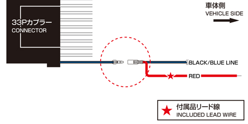
CAPTION:3G 1番・「黒色/青色ライン」のリード線加工 / NO.1 BLACK - BLUE LEAD WIRE MODS
続いて1番「黒色/青色ライン」のリード線を切断し、上記の加工手順で記載した通り、リード線にスリーブ、ギボシを取り付けます。ギボシはカプラー側(ECU側)にオス、車体ハーネス側にメスとなりますが、車体ハーネス側のメスギボシはI-MAPに付属されている「赤色」のリード線もまとめて、ギボシを圧着します。
Cut No.1 "BLACK/BLUE" lead wire, install sleeve and couplers as written above. Male coupler is crimped on ECU side, female is for vehicle side together with "RED" lead wire that includes in I-MAP.
 図のリード線を加工します。
Make modification of left lead wire
一連の加工動作です。/ WIRE MODIFICATION
1
カットする
Cut the wire
2
被膜を剥がす
Remove coating
3
スリーブ(オス)を入れる
Insert sleeve (male)
4
ギボシ(オス)を圧着する
Crimp coupler (male)
5
ギボシ(オス)完成
Coupler (male) finished
6
スリーブ(メス)を入れる
Insert sleeve (female)
7
ギボシ(メス)を圧着する
Crimp coupler (female)
8
ギボシ(メス)完成
Coupler (female) finished
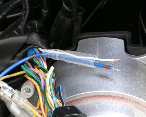
CAPTION:4A I-MAPに付属している「灰色」、「白色」のリード線加工 / GRAY - WHITE (INCLUDED IN I-MAP) MODS.
次にI-MAPに付属している「灰色」のリード線にスリーブ、メスギボシ、「白色」のリード線にスリーブ、オススギボシを取り付けます。
Connect sleeve and female coupler on "GRAY" lead wire (included with i-map). Connect sleeve and male coupler on "WHITE" lead wire.
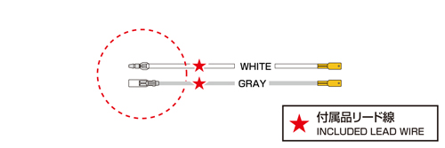 図のリード線を加工します。
Make modification of left lead wire.
一連の加工動作です。/ WIRE MODIFICATION
1
スリーブ(メス)を入れる
Insert sleeve (female)
2
ギボシ(メス)を圧着する
Crimp coupler (female)
3
ギボシ(メス)完成
Coupler (female) finished
4
スリーブ(オス)を入れる
Insert sleeve (male)
5
ギボシ(オス)を圧着する
Crimp coupler (male)
6
ギボシ(オス)完成
Coupler (male) finished
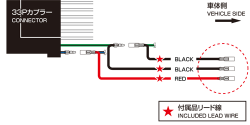
CAPTION:4B I-MAPに付属している「黒色」、「赤色」のリード線加工 / BLACK - RED LEAD WIRE (INCLUDED IN I-MAP) MODS
前の工程で結線したI-MAPに付属している「黒色」リード線2本と「赤色」リード線1本の被膜を剥がして、スリーブ、メスギボシを取り付けます。
Crimp sleeve and female coupler on 2 of "BLACK" lead wires that were connected with previous procedure. Crimp sleeve and female coupler on "RED" lead wire.
 図のリード線を加工します。
Make modification of left lead wire.
一連の加工動作です。/ WIRE MODIFICATION
1

被膜を剥がす
Remove coating
2
スリーブ(メス)を入れる
Insert sleeve (female)
3
ギボシ(メス)を圧着する
Crimp coupler (female)
4
ギボシ(メス)完成
Coupler (female) finished
CAPTION:4C I-MAP本体から出ている「黒色」、「赤色」のリード線加工 / BLACK - RED LEAD WIRE (THAT COME FROM I-MAP) MODS
次はI-MAP本体から出ている「黒色」リード線2本と「赤色」リード線1本にスリーブ、オスギボシを取り付けます。
これで配線加工作業は終了です。これから加工したリード線の接続作業となります。
Crimp sleeve and male coupler on 2 of "BLACK" wires and "RED" lead wire that come from i-map.
Wiring mods is all done.
 図のリード線を加工します。
Make modification of left lead wire.
一連の加工動作です。/ WIRE MODIFICATION
1
スリーブ(オス)を入れる
Insert sleeve (male)
2
ギボシ(オス)を圧着する
Crimp coupler (male)
3
ギボシ(オス)完成
Coupler (male) finished
CAPTION:5A リード線の結線その1 / WIRING LEAD WIRE 1
まず、16番の「桃色/緑色ライン」のリード線のオスギボシ(カプラー側)にI-MAPに付属している「灰色」リード線を、同じくメスギボシ(車体側)にI-MAPに付属している「白色」リード線を接続します。
Connect "GRAY" lead wire included in I-MAP to No.16 "PINK/GREEN" line male coupler. Connect "WHITE" lead wire included in I-MAP to female coupler on vehicle side.
 図のリード線同士を結線します。
Connect lead wire left.
一連の結線動作です。/ WIRE MODIFICATION
1
「桃色/緑色ライン」のオス側と「灰色」を結線
Connect "PINK/GREEN" male coupler with "GRAY" lead wire.
2
「桃色/緑色ライン」のメス側と「白色」を結線
Connect "PINK/GREEN" female coupler with "WHITE" lead wire.
CAPTION:5B リード線の結線その2 / WIRING LEAD WIRE 2
次に5番「黄色」のリード線、22番「白色/青色ライン」のリード線、2番「緑色/黒色ライン」、1番「黒色/青色ライン」のリード線をそれぞれ同じ色同士接続します。
Connect No.5 "YELLOW" lead wire, No.22 "WHITE/BLUE" lead wire & No.1 "BLACK/BLUE" line to same color couplers.
 図のリード線同士を結線します。
Connect lead wire left.
一連の結線動作です。/ WIRE MODIFICATION
1
「黄色」同士を結線
Connect "YELLOW" with the same color.
2
「白色/青色ライン」同士を結線
Connect "WHITE/BLUE" with the same color.
3
「青色/黄色ライン」同士を結線
Connect "BLUE/YELLOW" the same color.
4
「緑色/黒色ライン」同士を結線
Connect "GREEN/BLACK" with the same color.
5
「黒色/青ライン」同士を結線
Connect "BLACK/BLUE" with the same color.
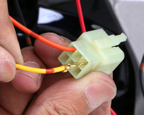
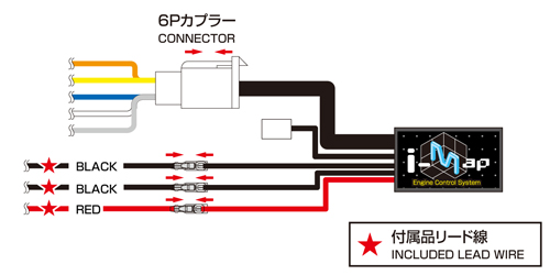
CAPTION:5C 6Pカプラーへの平端子の差し込み / INSERT FLAT TERMINAL TO 6P COUPLER
前の工程で結線した付属品のリード線の平端子側を付属の6Pカプラー(オス)に差し込みます。差し込み箇所を間違えないように注意して下さい。
Insert lead wire flat terminals that crimped with previous procedure to 6P coupler that comes with I-MAP. Do not misconnect it.
 図の位置に平端子を差し込みます。
Insert flat terminals.
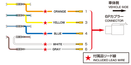
 平端子の差し込みには向きがあります。平端子に抜け防止の爪がありますので、凸型の穴に合わせて奥まで差し込み、爪が引っかかっているか確認して下さい。
Flat terminal has direction. There is falling prevention pawls on them. Make sure that pawls is tangled.
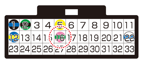
一連の差し込み動作です。2番は空きスペースとなります。/ NO WIRE INSERTS NO.2.
1
2
「橙色」を差し込む
Insert ""ORANGE""
3
「黄色」を差し込む
Insert "YELLOW"
4
「青色」を差し込む
Insert "BLUE"
5
「白色」を差し込む
Insert "WHITE"
6
「灰色」を差し込む
Insert "GRAY"
7
差し込み完成
Insert finished
しまった!差し込む位置を間違えた! / NO WAY ! WRONG INSERT !
平端子の差し込み位置を間違えた場合、やり直しは利きます。図の様に爪がフックとなり、カプラーに平端子が固定されている訳ですが、千枚通し等の細い棒等で、爪を押さえれば平端子を引き抜く事ができます。
When flat terminal is inserted to the wrong place, it is OK. You can fix this out. If you push down the pawl from the other side with thin stick such as an eyeletter, it can be pulled out.
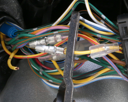
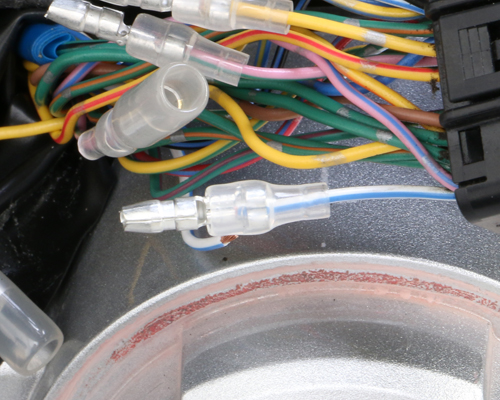
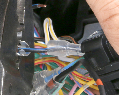
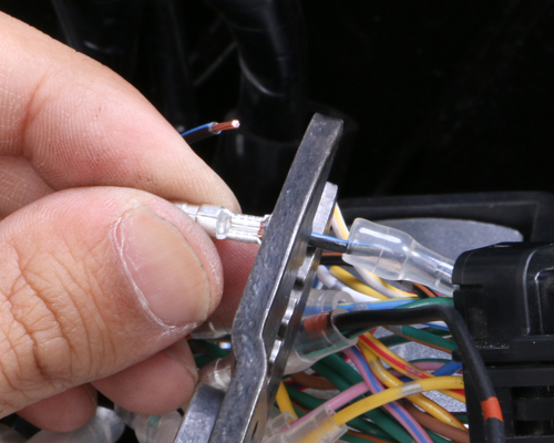
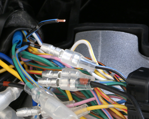
CAPTION:6A 保護テープの巻付け / PROTECTION TAPE
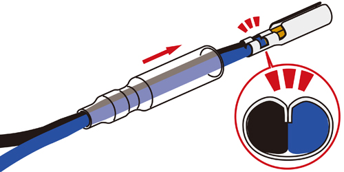
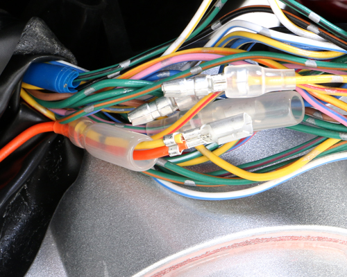
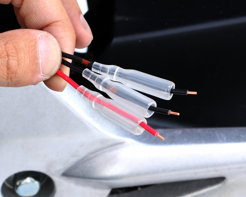
剥がした保護テープの箇所をハーネステープを使用して、ハーネスをまとめます。
Bandle harnesses with harness tapes.
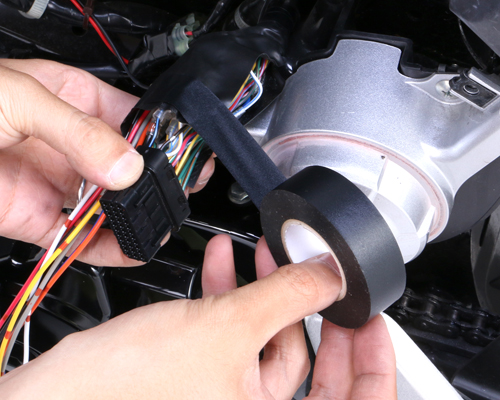
 剥がした保護チューブを補修するように結線したギボシ部分も含めてまとめておきます。
Bandle harnesses together with couplers, so to repair protection tube.
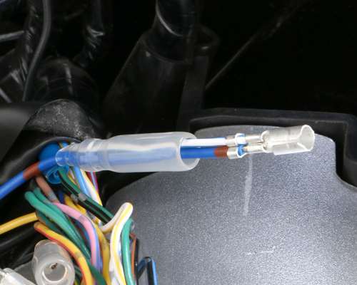
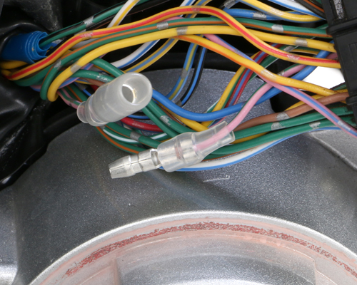
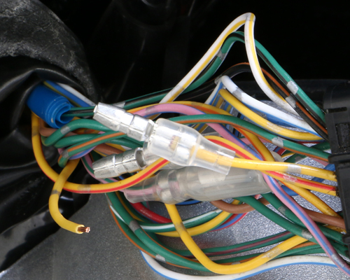
CAPTION:6B 33Pカプラーの接続と6Pカプラーとリード線3本の取り回し
33P COUPLER CONNECTION & REROUTING OF 6P COUPLER & 3 LEAD WIRES.
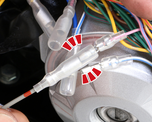
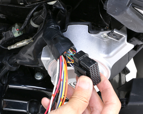
33PカプラーをECUに接続し、結線した6Pカプラーとリード線3本をフレームの内側を通して、シート下まで取り回します。
Connect 33P coupler, put the connected 6P coupler and 3 lead wires inside the frame, reroute under seat.
CAPTION:6C I-MAPとの接続 / CONNECT WITH I-MAP
I-MAP本体と6Pカプラー、リード線を同じ色同士接続します。
Connect I-MAP & 6P coupler. Connect same color lead wires.
 図のカプラー、リード線同士を結線します。
Connect the coupler with other coupler. Connect the lead wire with other lead wire.
一連の結線動作です。/ WIRE MODIFICATION
1
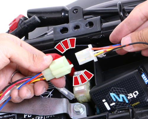
6Pカプラーを接続
Connect 6P couplers
2
「黒色」同士を結線
Connect "BLACK" with "BLACK"
3
「黒色」同士を結線
Connect "BLACK" with "BLACK"
4
「赤色」同士を結線
Connect "RED" with "RED"
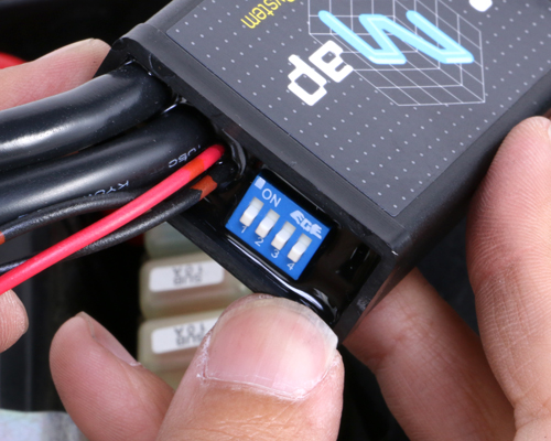
CAPTION:6D DIPスイッチの確認 / DIP SWITCH
接続後、説明書のDIPスイッチのパターンに従って、スイッチの位置を確認します。
After connecting, make sure that the DIP switch is in correct position, refering to instruction.
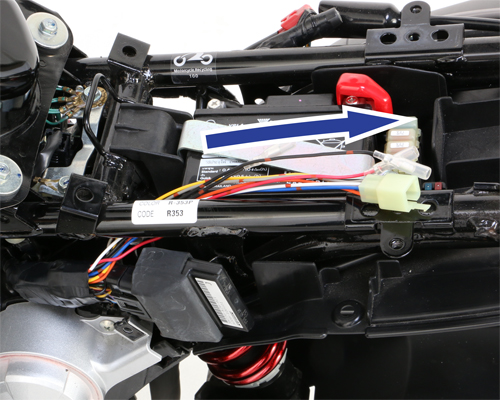
CAPTION:6E I-MAP本体の取付 / INSTALLING I-MAP
I-MAP本体はクッション材を使用して車体に取り付けます。グロムの場合、シート下の工具トレーを利用すると収まります。
Install I-MAP to vehicle, wrapped with cushion material. For GROM, tool tray under seat is good place to hold.
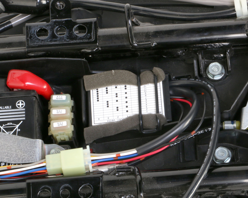
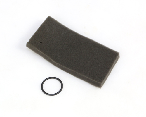 クッション材は衝撃を緩和するものならなんでも結構です。また汎用のクッション材は当社でも取り扱っています。
Any cushion material to soften the shock or vibration is ok. Universal cushion material is sold at Kitaco.
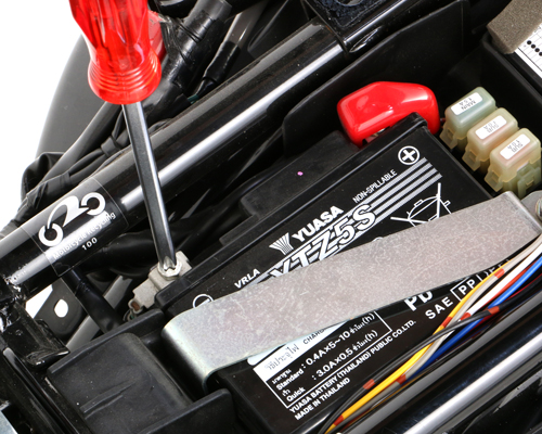
CAPTION:6F バッテリー端子の取付とエンジン始動 / INSTALLING BATTERY TERMINALS & START ENGINE.
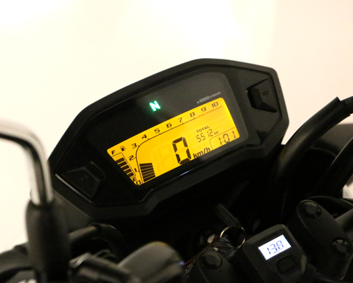
バッテリー端子を(+)端子側から取り付けて、メインキーをONにし、FI警告ランプの点灯が無く、エンジンが掛かれば完了です。
Install battery terminal (+) first & turn on the main key. If FI alarm lamp does not flush and engine starts, installation is finally finished.
あとは取り外した外装部品(CAPTION:1A~1E)を逆手順で取り付けて作業終了です。
Install the removed plastic parts (CAPTION:1A~1E) in reverse order.