

この項目はオリジナル燃調マップの作成を実践しながら解説していきます。 How to make original air / fuel map
必要なセットアップが終了すると、次はいよいよオリジナル燃調マップの作成に移ります。まずは燃調マップのおおまかな流れについて説明します。 Next is to make original map. Let's try a few more !


BEFORE MAKING ORIGINAL MAP...
燃調マップの作成は前の項目でも説明しましたが、実走行によるデータ収集とパソコンでの燃調マップ作成作業の繰り返しです。結構根気のいる作業ですので、諦めずに行う心構えが必要です。
それとセッティングを間違えるとエンジンを損傷させてしまう恐れもありますので、説明を理解した上で作業に取り掛かって下さい。また、作業には実走行を伴います。一般公道で行うのは危険が伴いますので絶対にお止め下さい。作業はサーキットもしくは広い私有地等で安全を確認しながら行いましょう。
It requires collecting actual running data & making air / fuel map continuously. Please make sure to understand the I-MAP function before installing. Please operate at race circuit or large private property . Do not try on the public street.

Fig.A Summary of making original map
具体的な作業の流れとしましては「実走行を行う」→「測定すべき回転数、スロットル開度時のA/F数値を確認する」→「A/F数値を参考にパソコンで燃調マップを修正する」→「I-MAPに書き込む」と言った作業の繰り返しとなります。 To be more specific, setting I-MAP requires "actual run" "A/F number confirmation at specific revolving area & specific throttle opening", "correct A/F number" & "write to I-MAP", again and again.
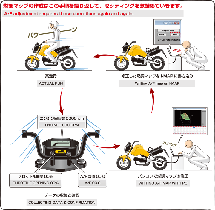

Fig.B-1 Choosing pre-installed map
一からのオリジナル燃調マップ作成は非常に手間と時間が掛かります。ですのでオリジナル燃調マップの作成の近道としては、I-MAPにすでにプリインストールされている燃調マップをベースに作成する方をオススメします。
まず、今現在の車両のチューニング内容とI-MAPのプリインストールされている燃調マップを見比べて、内容が近い燃調マップを選びましょう。
It takes a lot of time to make original map from zero, so install "pre-installed map" which looks similar to your tuning level.
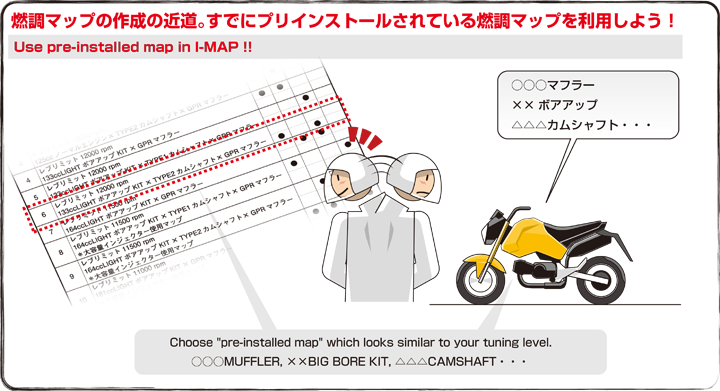

Fig.B-2 Setup I-MAP
上記で選んだ燃調マップを、付属の取付説明書を参考にI-MAP本体のディップスイッチで選択し、PCインターフェイスケーブルでI-MAP本体とパソコンを接続、車両のメインスイッチをONにします。
Choose a pre-installed map with DIP SWITCH on I-MAP body, connect I-MAP to PC with PC INTERFACE CABLE and turn on the main switch.
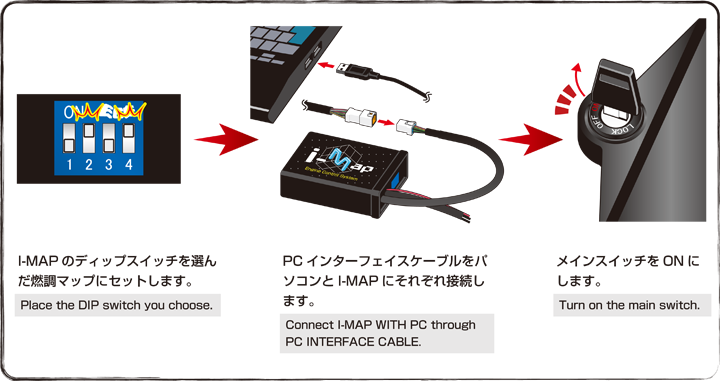

この時エンジンは作動させないで下さい。車両のメインスイッチをON(I-MAPに電源を通すだけ)にするだけで結構です。エンジン作動中(I-MAP作動中)にパソコンでデータ書き込み作業を行うと、I-MAPの破損にもつながりますのでお止め下さい。 Please do not start the engine, just turn on the main switch (through I-MAP) is enough. The operation while engine is on (while I-MAP is working) will break I-MAP.

Fig.B-3 Reading & Writing exiting map.
パソコン側ではFUEL MANAGERを立ち上げます。
Readボタンをクリックすると、先ほどI-MAPのディップスイッチで選んだ燃調マップがFUEL MANAGERに読み込まれます。
この燃調マップをベースに車両のチューニング内容に合わせた燃調マップを構築していきましょう。
その読み込んだ燃調マップのままWriteボタンをクリックすると、I-MAPに本体のユーザーマップチャンネルに自動的に書き込まれます。
Start "FUEL MANAGER" on PC. Press "Read" button to read the map you chose to start "FUEL MANAGER". If "Write" button is pressed, the same map will be written on I-MAP user channel.

ちなみにI-MAPへの書き込みはユーザーマップチャンネルのみとなります。すでにプリインストールされている燃調マップチャンネルに上書きはできません。
You can write only on "USER MAP CHANNEL". Not able to overwite pre-installed map.

Fig.B-4 Change of USER MAP CHANNEL
次に車両のメインスイッチをOFFにし、I-MAPからPCインターフェイスケーブルを外して、I-MAPのディップスイッチをユーザーマップのチャンネルに合わせます。
ユーザーマップチャンネルはI-MAPのモデルにより様々です。詳しくはI-MAPに付属している取付説明書を参考にディップスイッチをセットして下さい。
Then turn off the switch, remove I-MAP from PC INTERFACE CABLE and put DIP SWITCH to user channel. The position of DIP SWITCH combination of user channel is different according to the models. Please refer to instruction manual for the details.
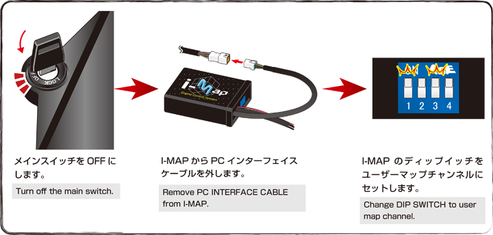

Fig.C-1 Saving map
燃調マップはパソコンに保存もできます。「File→Save」を選び、保存の際のファイル名は任意の名前でOKです。保存すると、fmpファイルとして保存されます。 Air/Fuel map is saved to PC. Choose "Save" on "File" tab with your specified name. The file is saved as .fmp file.
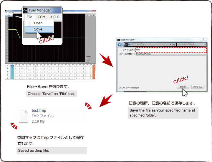

Fig.C-2 Opening fuel/air map
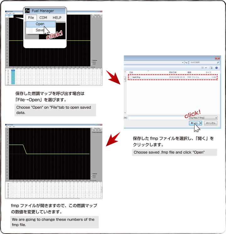
保存したデータを呼び出す場合はFUEL MANAGERを立ち上げて、「File→Open」を選び、「保存したfmpデータを選択→開く」をクリックすると、燃調マップが開きます。この先作業を進める上で、保存と呼び出し作業は覚えておきましょう。
Start "Fuel Manager", choose "Open" on File tab, choose fmp saved data.

LET'S MAKE ORIGINAL FUEL MAP !
さて、これから実走行によるデータ取りを開始しますが、その前にデータの取り方や燃調マップの煮詰め方を解説していきます。
Let's explain how to collect required data & adjustment.

Fig.D-1 What is required with data collecting?
データ取りとはスロットル開度が〇〇%で、エンジン回転数が〇〇〇〇rpmの時、A/F数値が○○.○と走行しながら確認していく作業です。全ての回転域、スロットル開度で最適なA/F数値に調整する事が燃調マップの作成にあたります。
A/F数値は燃料1に対しての、酸素量の対比数値です。理論上の理想空燃比は14.7とされていますが、あくまでも理論上であり、
実走行上では13.5前後を目指して下さい。このA/F数値13.5前後より、値の大きい方が燃料が「薄い」、小さいが「濃い」となります。
"Required data collecting" means the information that A/F number is ○○.○ at ○○% throttle opening, at △△△△ rpm and so on. You need to try to fill in the best number in all rpm range as well as all throttle opening of your vehicle. A/F number is "the fuel amount compared to oxygen".
For actual running, try to make around 13.5. If number increased, it means "LEAN". If decreased, it means "RICH".
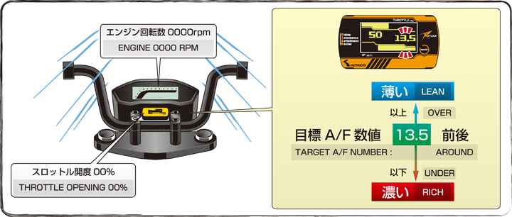

Fig.D-2 Procedure of data collecting
スロットル開度は5%刻み、エンジン回転数は500rpm刻みで調整が可能ですが、全回転域、全スロットル開度でデータを取るのは非常に手間と時間が掛かりますので、最初はスロットル開度別に0%、25%、50%、75%、100%と区切ってデータ取りしていきます。スロットル開度の回せる範囲内のエンジン回転数を1000rpm置きと区切ってデータ取りをしていき、徐々に煮詰めていきましょう。
また、走行後得られたA/F数値をメモしていく事も燃調マップを構築する上でオススメします。
The writable number of throttle opening is adjusted by 5%, engine revolusion is by 500 rpm, but calculating all the revolusion & all throttle opening takes too much time. First, let's collect data by 0%,25%, 50%, 75% 100% of throttle opening.


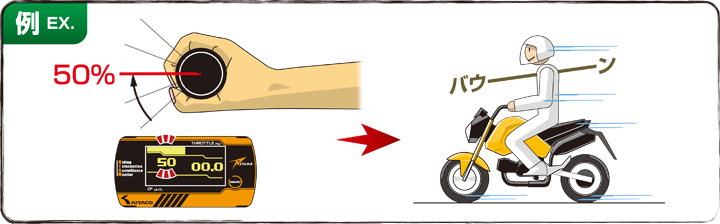
Fig.E-1 50% throttle opening for test
それではまず、試しにスロットル開度50%でデータ取りを行ってみましょう。
下記からの説明は燃調マップの作成手順を理解しやすいようにまとめた例です。実際には車両、チューニング内容により、A/F数値、燃調の%の値は様々です。ですので、
例えA/F数値が14.0だとしても、数%増やすと決まった数値はありません。
スロットル開度50%ではエンジンを回せる範囲が限られてきますので、回せる範囲内でのデータ取りとなります。
Let's collect data with 50% throttle opening. Following is the example data for reference. The A/F number & percentage depends on how you tune your vehicle. It is not like you need to increase certain amount with certain A/F number.
There is no specified percentage even if A/F number is 14.0 and so on.
With 50% throttle opening, engine does not rev so high, which mean the collecting data with that revving range.
エンジンは十分な暖機を行ってから、実走行でのデータ取りに移って下さい。エンジンが冷えている状態ですと、A/F数値が安定しません。
Warming up the engine before collecting data of actual run. With cold engine, A/F number is not stable.

Fig.E-2 Collecting data the 1st time.
データ取りしてみていかがでしたでしょうか?
下記の例ではスロットル開度50%の実走行では3000rpmでA/F12.8、4000rpmでA/F12.8、5000rpmでA/F13.2、6000rpmでA/F13.5、7000rpmでA/F13.8、8000rpmでA/F14.0と表示されました。
すなわち3000~5000rpmでは濃い、6000rpmではちょうど良い、7000~8000rpmでは薄いと言う事になります。
How was the collected data?
Following example data shows : A/F 12.8 at 3,000 rpm, A/F 12.8 at 4,000 rpm, A/F 13.2 at 5,000 rpm, A/F 13.5 at 6,000 rpm, A/F 13.8 at 7,000 rpm & A/F 14.0 at 8,000 rpm
In another words, "RICH" around 3,000 ~ 5,000 rpm, "GOOD" at 6,000 rpm & "LEAN" around 7,000 ~ 8,000 rpm with 50% throttle opening.
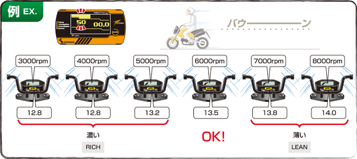

Fig.E-3 Correcting data the 1st time
次にパソコンで燃調マップの修正を行いますので、FUEL MANAGERを立ち上げて作業を行います。(fmpデータを保存している場合はFig.C-2を参考に呼び出して下さい。)
先ほどデータ取りしたエリアはスロットル開度50%で、エンジン回転数3000rpm~8000rpmでしたので、その該当するエリアを修正していきます。
3000rpm~5000rpmの時では濃かったので、3000rpm・10%→-10%に、4000rpm・10%→-10%に、5000rpm・10%→0%に、6000rpmではちょうど良かったのでそのままに、7000rpm~8000rpmでは薄かったので、7000rpm・10%→20%、8000rpm・10%→25%にしてみます。
500rpm刻みの部分には回転数前後の中間あたりの数値に変更してみましょう。
Start the FUEL MANAGER to correct the A/F map. Open fmp file if you have already saved, refering to Fig.C-2.
Let's correct the areas with the data you collected, which is from 3,000 ~ 8,000 rpm at 50% throttle opening.
Input "-10%" from 10% at 3,000 ~ 4,000 rpm as these ranges were too rich. Input "0%" from 10% at 5,000 rpm. Stay the same number at 6,000 rpm as the number was good. "20%" from 10% at 7,000 ~ 8,000 rpm & "25%" from 10% at 8,000 rpm as these ranges were too lean.
Input midium number at 500rpm range.
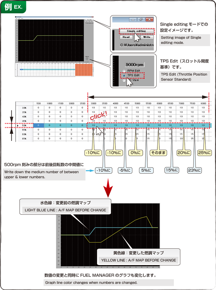

Fig.E-4 Overwrite the corrected data on I-MAP
先ほどと同様の手順で、PCインターフェイスケーブルをI-MAPに接続し、車両のメインスイッチをON、そしてFUEL MANAGER上でWriteボタンをクリックして修正した燃調マップをI-MAPに書き込みます。
Connect I-MAP with PC using PC INTERFACE CABLE. Turn on the main switch, click "Write" button to overwrite the corrected map on I-MAP.
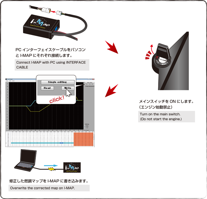

Fig.E-5 Collecting data the 2nd time
I-MAPからPCインターフェイスケーブルを外し、もう一度、先ほどのスロットル開度50%で走ってみます。
すると下記の例では3000rpmでA/F13.4、4000rpmでA/F13.5、6000rpmでA/F13.5、7000rpmでA/F13.5、8000rpmでA/F13.8と表示されました。3000rpm~7000rpmではこれでOKですが、8000rpmではまだ薄い数値です。
Remove PC INTERFACE CABLE from I-MAP & run with 50% throttle opening again. Following data shows : A/F 13.4 at 3,000 rpm, A/F 13.5 at 4,000 rpm, A/F 13.5 at 6,000 rpm, A/F 13.5 at 7,000 rpm & A/F 13.8 at 8,000 rpm. It is okay at 3,000 ~ 7,000 rpm range, but it is still lean (A/F 13.8) at 8,000 rpm.
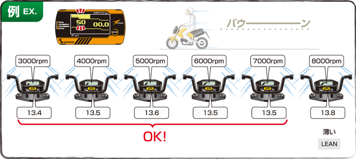

Fig.E-6 Correcting data the 2nd time
もう一度、同じようにFUEL MANAGERでスロットル開度50%の該当するセルを8000rpm・25%→30%に、7500rpm・23%→25%に変更してみます。
修正後、Fig.E-4を参照に修正した燃調マップを再度I-MAPに書き込みます。
Input "30%" from 25% at 8,000 rpm, "25%" from 23% at 7,500 rpm range. After finishing the adjustment, overwrite the map on I-MAP refering to Fig.E-4.
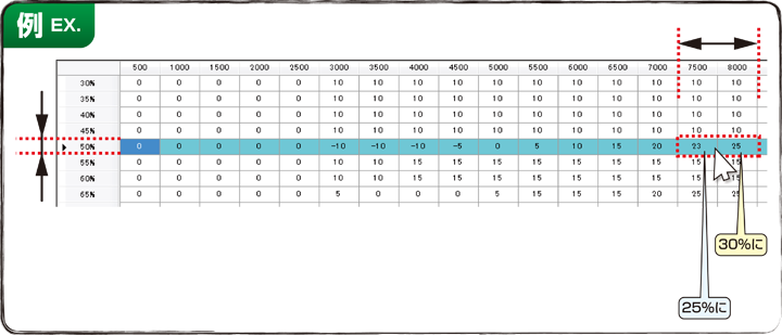

Fig.E-7 Collecting data the 3rd time
さらにもう一度スロットル開度50%で走ってみます。下記の例では8000rpmでA/F13.6と表示されました。これでスロットル開度50%、3000rpm~8000rpmの部分の燃調はOKです。
以上が燃調マップ作成の一連の作業となります。
Then drive with 50% throttle opening again. The following reference says A/F 13.6 at 8,000 rpm, which means the air/fuel adjustment around 3,000 ~ 8,000 rpm with 50% throttle opening is finished.
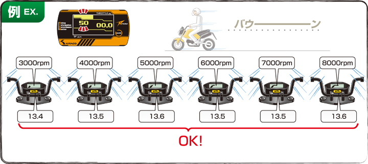

Fig.E-8 More adjustment in details.
次に上記Fig.E-2~Fig.E-7までの手順で他のスロットル開度100%、75%、25%、0%とセッティングを出していきます。
その間のスロットル開度(95%~80%・70%~55%・45%~30%・20%~5%)はすでにセッティングの出ているスロットル開度の中間値を目安として書き込み、A/F数値を確認していきましょう。この様に実走行とA/F数値確認、燃調マップの修正を繰り返す事で煮詰めていきます。
Next, like Fig.E-2 ~ Fig.E-7, set-up the adjustment of throttle opening 100%, 75%, 25% & 0% as well.
Input the midium number on the throttle openings between them (95% ~ 80%, 70% ~ 55%, 45% ~ 30%, 20% ~ 5%) as rough standard. Finalize A/F numbers step by step with collecting data and actual run in turn.


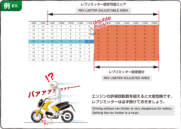
Fig.F Setting rev-limiter
FUEL MANAGERでは9000rpm以上の回転域で任意に燃料噴射を停止させるレブリミッター機能が備わっています。
9000rpm以上のセルをダブルクリックすると、その先がオレンジ色に変わり、オレンジ色の部分は燃料噴射を停止します。
レブリミッターの設定は非常に重要です。エンジンの仕様によりリミッターをかける回転数は様々ですが、エンジン保護のためにも必ず設定して下さい。
FUEL MANAGERでは最大15000rpmまで燃料噴射の設定が可能ですが、15000rpmまで燃調マップを設定しても、そこまでのエンジン回転を保障するものではありません。許容回転数はエンジンの仕様により異なります。特にノーマルエンジン(シリンダーヘッド等)では許容回転数は高く設定されていませんので、それを超えてエンジンを回すと、バルブサージング(バルブの開閉がカムシャフトの動きに追従できなくなる現象)が発生し、エンジンを破損してしまう恐れがあります。
具体的にはバルブサージングが発生するとシリンダーヘッドからチリチリ・・と言う異音が発生します。異音が発生する前の回転数からレブリミッターを掛けて下さい。
Setting rev-limiter is a must, very important. With FUEL MANAGER, you can make arbitary rev limit over 9,000 rpm.
You must make rev limit to protect your engine.
The adjustable maximum rpm is 15,000 rpm, but it is not guaranteed that our engine revs up to the point. Especially, stock engine (stock cylinderhead) does not rev up so high for protection. Once revving over the certain rpm, valve surging might occur, which causes engine breakage.